
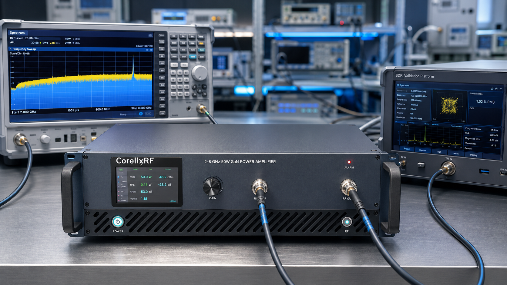
Application notes should begin with the setup, not the catalog line. Picture a wideband lab bench where one signal source must drive several test cases from 2 to 8 GHz: SDR chain validation in one run, communication subsystem checks in another, and controlled RF output tests after that. The CRF-PA-2000M8000M-50W fits this kind of environment as a 2-8 GHz 50W GaN RF amplifier with enough bandwidth to reduce amplifier swaps while keeping the system in a manageable 3U rack-mount format.
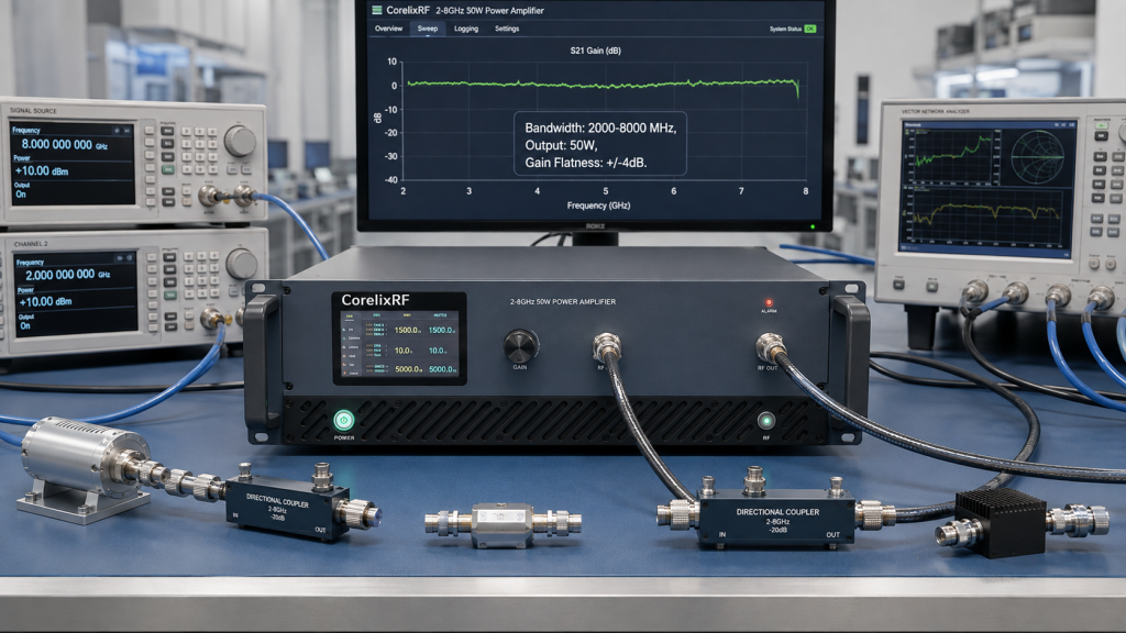
The amplifier’s published baseline includes 2,000-8,000 MHz frequency coverage, 50 W rated RF output power, 47 dB minimum small-signal gain, +/-4 dB gain flatness, up to 20 dB gain control, N-Female input/output connectors, RS485/LAN control, AC 220 V supply, and air cooling. For teams comparing wideband microwave hardware with lower-band UHF amplifier options, the key decision is whether the test bench really benefits from continuous 2-8 GHz coverage.
Example Bench Architecture
A practical wideband test bench may look like this:
Signal source or SDR output -> level control/attenuation -> 2-8 GHz amplifier -> directional coupler -> load, antenna, chamber feed, or device under test -> power meter/spectrum analyzer.
The amplifier is one part of the chain. The upstream source must stay below the listed 0 dBm maximum input power. The downstream load must be rated for the output condition. Couplers, cables, adapters, and loads must cover the whole frequency span. If the project uses a switch matrix, include insertion loss and isolation in the RF budget.
CorelixRF’s RF testing and validation resource is a useful internal reference because it frames the amplifier as part of a source-amplifier-load-measurement system.
Why 50 W Can Be the Right Level
Not every 2-8 GHz project needs hundreds of watts. A 50 W RF power amplifier can be suitable when the goal is component validation, front-end stress testing, communication chain review, SDR output boosting, or controlled lab experiments. It provides enough output to move beyond low-level signal work while keeping the platform smaller than a high-power rack system.
The 47 dB minimum gain helps reduce the burden on the signal source. The 20 dB gain control range gives operators room to adjust output level without constantly changing external attenuation. That matters in a lab where multiple test plans share one rack.
Setup Step 1: Protect the Input
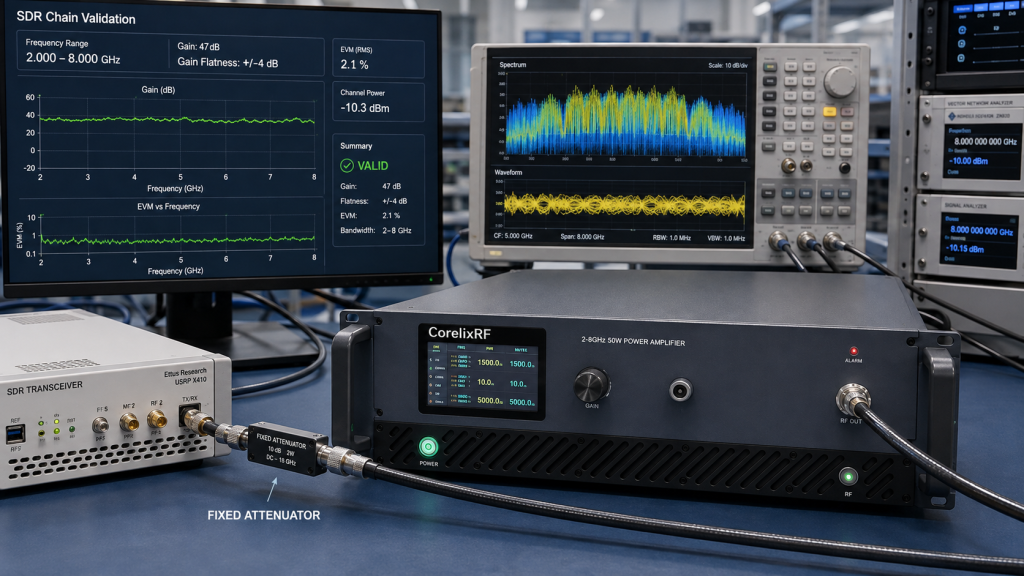
Before powering the amplifier, verify the source level at the amplifier input connector. The maximum input power is listed as 0 dBm. If an SDR, generator, or driver can exceed that level, use fixed attenuation and a controlled startup procedure. Label the source settings used for each test case so operators do not accidentally overdrive the chain.
For automated benches, interlock logic can be designed around source enable, amplifier enable, gain setting, and alarm status. If the project requires this level of control, include it when contacting CorelixRF through the Contact page.
Setup Step 2: Plan the Output Path
The amplifier uses N-Female input and output connectors. That is convenient for many lab setups, but the cable and load still need to be selected for 2-8 GHz operation. Loss and mismatch can change meaningfully across the band. If the output connects to an antenna, chamber feed, or DUT, describe that load in the RFQ.
The datasheet lists temperature monitoring, current monitoring, optional forward/reverse power monitoring, optional input power detection, and built-in protection. Forward/reverse power monitoring is especially useful when the output condition changes frequently.
Setup Step 3: Keep the Rack Boring
“Boring” is a compliment in RF racks. Give the 3U amplifier enough airflow, stable AC power, clear cable routing, and a repeatable grounding approach. The CRF-PA-2000M8000M-50W is air cooled and specified for 0 to +50 degrees C operation. Do not bury it behind hot equipment or block exhaust paths.
If the bench is expected to run long tests, document ambient temperature, duty cycle, output level, and failure thresholds. These details make it easier to decide whether a standard broadband RF power amplifier is enough or whether the project needs a custom configuration.
Acceptance Data to Request
For a wideband bench, ask for test data that matches the way the amplifier will actually be used. Useful evidence may include output power at representative frequencies, small-signal gain behavior, gain-control response, harmonic and spurious checks, alarm behavior, and thermal observations under the intended operating mode. If the test bench will be used for procurement acceptance or internal qualification, name the required test points in the first RFQ.
This also helps separate amplifier questions from fixture questions. If a weak result appears at 7.5 GHz, the cause might be the amplifier, cable loss, adapter quality, load mismatch, or calibration setup. A documented baseline makes troubleshooting cleaner and keeps the amplifier review grounded in measurable conditions.
FAQ
What is the focus keyword?
The focus keyword is 2-8 GHz 50W GaN RF amplifier.
What makes this article an application note?
It explains how the amplifier fits into a real wideband test bench instead of only listing specifications.
What input limit should be reviewed?
The datasheet lists 0 dBm maximum input power, so source level and attenuation should be checked before operation.
What applications fit this amplifier?
It can support wideband lab validation, SDR RF chains, communication testing, RF interference system-level testing, and aerospace control validation.
Where should a buyer send the bench details?
Use the CorelixRF Contact page and include source, load, frequency points, power target, control interface, cooling, and documentation needs.