
A 2-8 GHz 500 W RF power amplifier is not just a higher-power version of a lab amplifier. At this power level, the RF chain, cooling path, interlocks, connectors, control interface, and operating procedure all affect whether the installation is reliable and repeatable.
CorelixRF’s CRF-PA-2000M8000M-500W reference datasheet lists 2 GHz to 8 GHz coverage, 500 W rated output power, 57 dB minimum small-signal gain, N-F input, 7/16 output, forced-air cooling, temperature/current diagnostics, and alarm protection. These details make it a useful baseline for teams evaluating a high power RF amplifier for broadband test benches.
Define the test profile before choosing the amplifier
A high-power 2-8 GHz amplifier may be used for communications testing, RF interference and EW system-level testing, aerospace control validation, or general test and measurement instrumentation. Each use case creates a different stress profile. A swept test may care about repeatability across frequency. A waveform test may care about duty cycle, average power, and thermal recovery. A system-level test may care about remote alarms and safe shutdown.
That is why the RFQ should include waveform type, CW or pulsed operation, duty cycle, test duration, source power, target output power, and required margin. A broadband RF power amplifier can only be matched correctly when the operating profile is clear.
Treat connectors as part of the power design
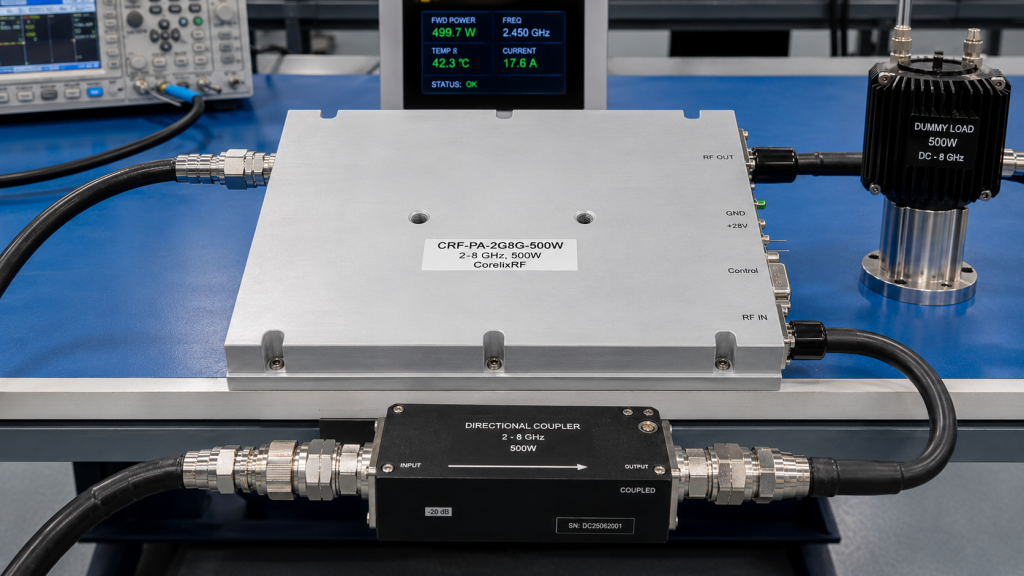
The 500 W reference configuration uses N-F input and 7/16 output. That output connector choice should prompt a review of cables, adapters, directional couplers, loads, and antenna fixtures. At hundreds of watts, connector mismatch and heat rise are operational risks, not minor accessories.
Before procurement, define the output connector preference and the downstream hardware. If the project requires a different interface, bring that into a custom RF development discussion instead of assuming the production configuration can be changed after acceptance testing.
Plan cooling and rack integration early
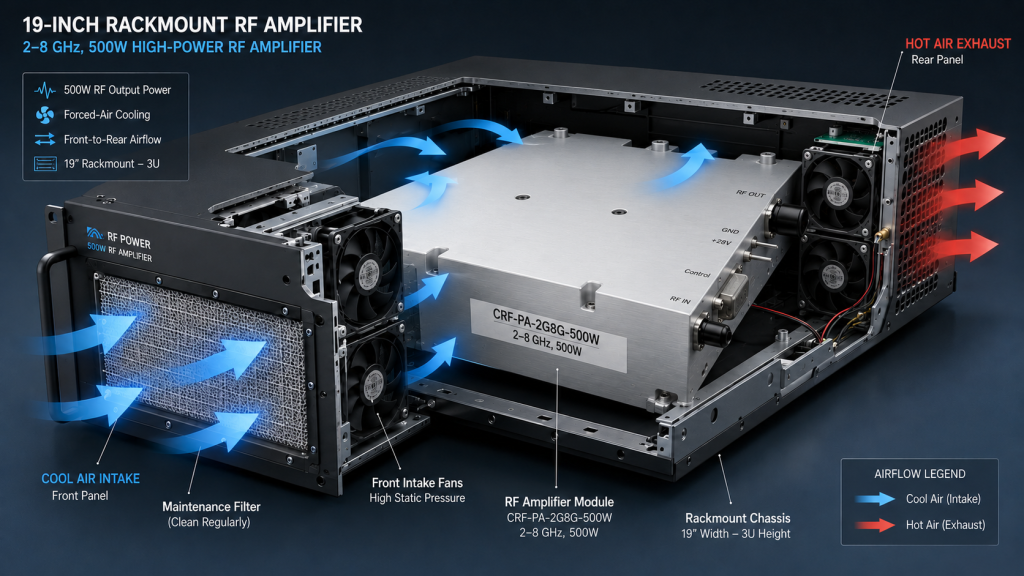
The reference specification identifies forced-air cooling and protection monitoring. For a high-power RF test bench, airflow direction, inlet temperature, rack spacing, filter maintenance, and alarm response should be written into the installation plan. If the amplifier is placed inside an enclosure, verify that the enclosure can remove the heat produced during the actual duty cycle.
A practical acceptance test should include the amplifier, RF load, couplers, control software, and alarm behavior. Teams using the amplifier in RF testing and validation should decide what the controller does when temperature, current, or alarm states are reported.
Compare 2-8 GHz with narrower alternatives
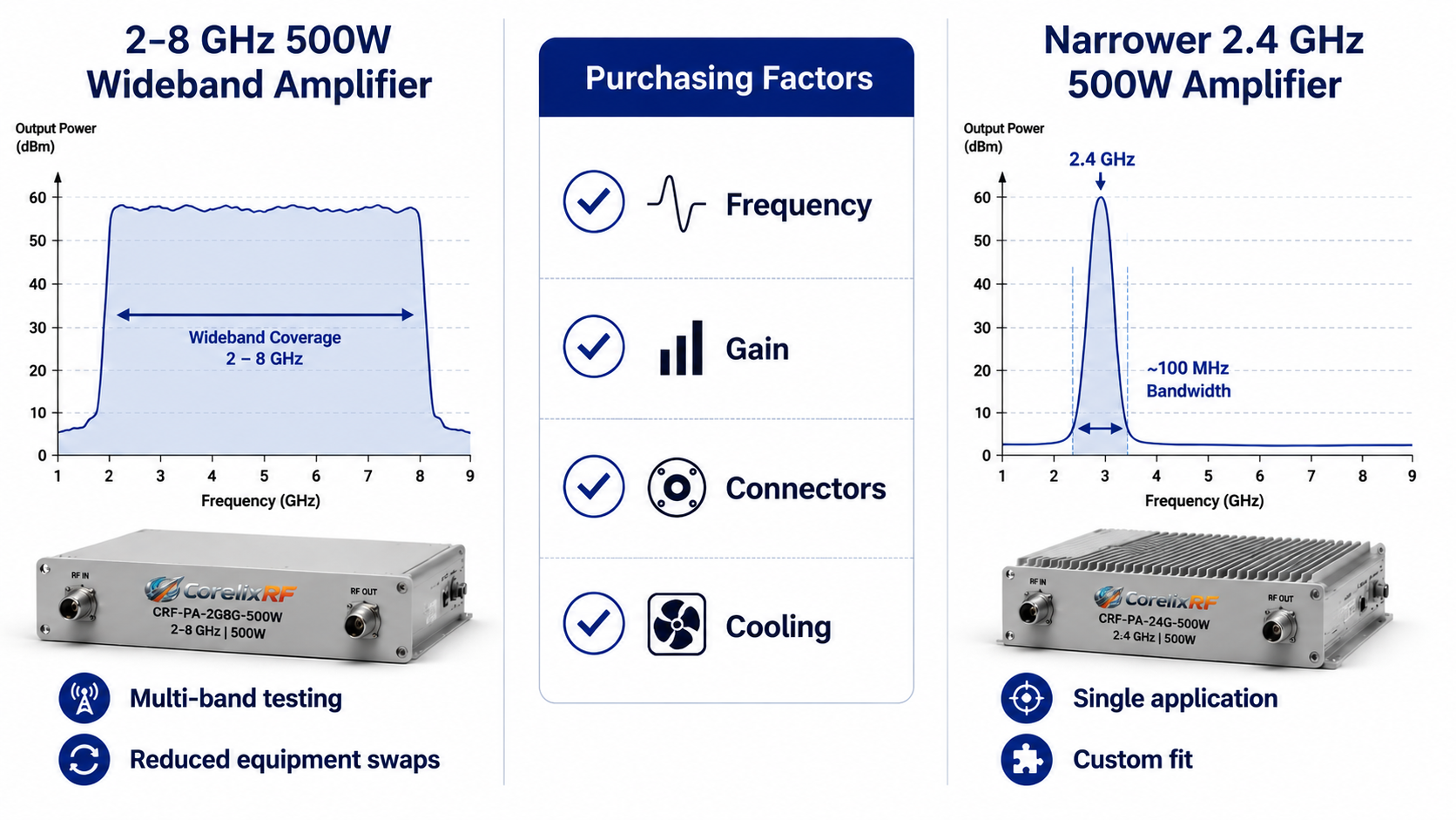
The value of 2-8 GHz coverage is flexibility. It can reduce equipment swaps and support multiple bands with one amplifier platform. The tradeoff is that a narrower amplifier may provide a better fit if the project only needs one small frequency window at very high power.
Engineers should compare standard RF power amplifier platforms against the actual frequency plan. If the system frequently changes between S-band and C-band experiments, the wideband choice may reduce complexity. If the project only runs one fixed channel, a narrower or custom amplifier may be more appropriate.
Protecting the device under test and the amplifier
A high-power broadband amplifier should be integrated with a clear operating procedure. The RF source should have output limits, the load or antenna path should be rated for the expected power, and operators should understand what happens if a mismatch, over-temperature state, or current alarm occurs. The amplifier’s protection features are valuable only when the rest of the test system responds correctly.
For automated benches, the control software should log amplifier state and prevent accidental overdrive during startup. A conservative commissioning sequence begins at low drive, verifies coupler readings, checks load temperature, confirms airflow, and only then approaches the required output level. This approach is slower during setup but reduces the chance of damaging fixtures or collecting invalid data.
What purchasing teams should compare
Purchasing teams often compare amplifiers by price and output power, but engineering risk is usually hidden in the details. For a 2-8 GHz 500 W amplifier, compare frequency coverage, minimum gain, RF connector configuration, cooling method, rack or enclosure assumptions, alarm reporting, lead time, and whether final test data will be supplied.
If two amplifier options appear similar, ask which one best fits the actual workflow. A lab that frequently changes bands may benefit from broadband coverage. A fixed-frequency production fixture may benefit from a narrower configuration. A system that must fit a restricted cabinet may need mechanical customization even when the RF parameters look standard.
FAQ
What is a 2-8 GHz 500 W RF power amplifier used for?
It is used for high-power broadband RF testing, communications validation, interference or EW test environments, and integrated RF systems that require wide S/C-band coverage.
Why does the output connector matter at 500 W?
The connector, cable, adapter, load, and coupler must be rated for the power and frequency range. A weak point in the output path can limit performance or create safety issues.
Should I specify CW or pulsed operation?
Yes. The amplifier supplier needs to know waveform type, duty cycle, and test duration because thermal and protection behavior depend on the operating mode.
Can CorelixRF review a custom configuration?
Yes. Provide the target band, power, waveform, cooling limits, connector requirements, control interface, and mechanical constraints for engineering review.