
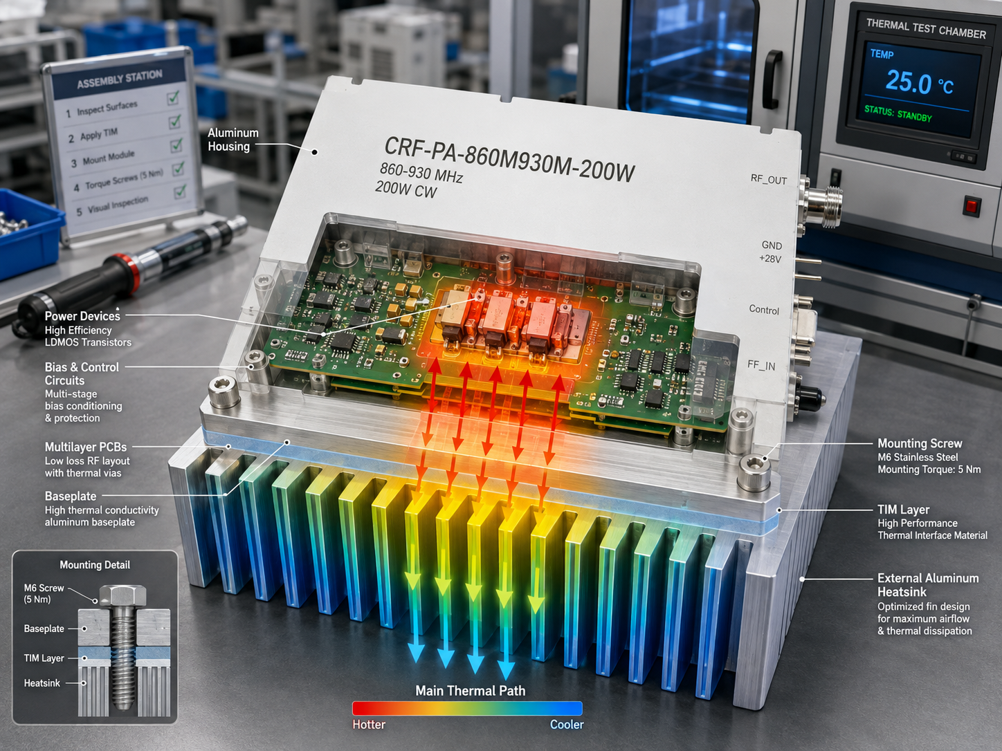
A narrowband amplifier article should not sound like a broadband amplifier article with a smaller frequency span. The design problem is different. In an 860-930 MHz module, the questions shift toward source architecture, gain adjustment, DC supply, heat sinking, control pins, PA enable timing, and protection logic. The CRF-PA-860M930M-200W is specified for 860 to 930 MHz with 200 W rated CW output power, and it is available in M/M1 amplifier-module configurations as well as a V version with an internal VCO source and 10 Hz stepping.
This makes it a strong fit for buyers reviewing CorelixRF’s narrowband amplifier options for communication systems, RF test equipment, or project-specific source integration. Instead of asking only “does it cover 860-930 MHz,” the better question is “which version fits the host system?”
Module Role: Amplifier Stage or RF Source Block?
The first decision is architectural. If the host system already provides a controlled RF source, the M or M1 amplifier-module path may be the right direction. If the project needs an internal VCO source and scan function, the V version becomes more relevant. The source datasheet lists 10 Hz stepping for the V version and frequency/bandwidth adjustment references from 760/30 to 960/180 MHz.
That difference changes the RFQ. A pure amplifier inquiry should describe the external source level, frequency stability, modulation, and enable logic. A source-integrated inquiry should describe tuning range, step size, scan behavior, control method, and output sequence.
Electrical Baseline
The datasheet lists 860-930 MHz frequency coverage, 160 W minimum and 200 W typical Psat, 49 dB minimum gain, 51 dB typical gain, and 53 dB maximum gain. Gain adjustment is listed as 20 dB with 0.5 dB step. Spurious output is listed at -60 dBc, and second/third harmonics are listed at -10 dBc.
For buyers comparing this model with a broadband RF power amplifier option, the narrowband design may be more appropriate when the system does not need wide coverage. A focused 860-930 MHz 200W narrowband RF amplifier can simplify source planning, filtering, and mechanical integration.
DC Power and Enable Timing
The amplifier operates from +24 V to +32 V with +28 V nominal supply. Typical current is listed at 30 A, with 36 A maximum. PA enable/disable time is listed at 100 microseconds maximum. These numbers belong in the system electrical design, not only in a procurement spreadsheet.
The DC path should be reviewed for voltage drop, connector current, startup behavior, sequencing, and protection margin. If multiple RF modules share one supply, identify the power-on order and whether the controller handles PA enable through hardware, software, or both.
Thermal Design Is Customer-Side Work
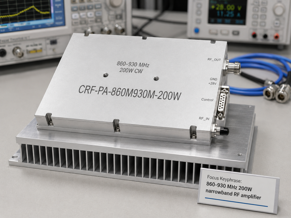
The mechanical size is 200 x 158 x 25 mm, with 1.4 kg listed weight. Cooling is external heat sink. That means the final host system must provide the thermal path. Heat-sink size, baseplate flatness, thermal interface material, mounting pressure, airflow, and ambient temperature all affect reliability.
The datasheet lists -40 to +60 degrees C operation and storage from -55 to +85 degrees C. It also references 95% RH non-condensing and environmental methods for altitude, vibration, and shock. Treat these as review inputs. Final qualification should match the actual application.
Control and Protection
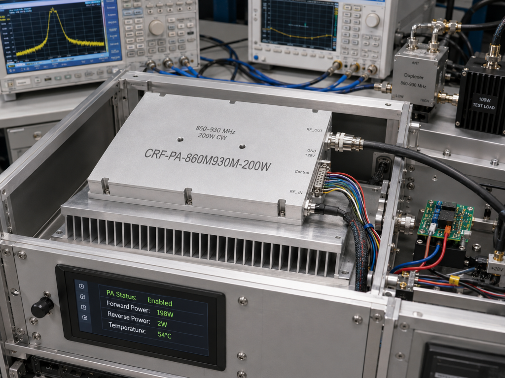
The D-Sub 15-pin female interface can support PA enable, alarm outputs, alarm reset, optional RS485, gain/power adjustment, Pf/Pr monitoring, and temperature output where applicable. The source data also lists over-temperature shutdown/recovery, over-VSWR locked shutdown, over-voltage lock above 32 V, and over-current lock above 38 A.
This is where a narrowband module can be nicely engineered or deeply annoying. Pinout, logic levels, reset behavior, analog outputs, and monitoring expectations should be finalized before the mechanical design is frozen. Send those requirements through CorelixRF Contact with the intended version: M, M1, or V.
What to Ask CorelixRF
Ask for the version recommendation, outline drawing, thermal guidance, interface definition, control logic, alarm behavior, gain-control method, test data, and any required project documentation. If the application is a communication subsystem or RF source product, include enclosure constraints and expected duty profile.
For related lower-frequency or UHF work, the UHF amplifier resource helps frame where this 860-930 MHz platform sits inside CorelixRF’s broader amplifier coverage.
Integration Review Sequence
A practical review sequence is simple. First, confirm whether the system needs M, M1, or V behavior. Second, confirm the RF source and output path. Third, confirm the DC supply, PA enable logic, and alarm handling. Fourth, review heat-sink design and mounting. Fifth, request the test data and interface documents needed for internal approval.
This order prevents a common narrowband mistake: locking the mechanical package before the control version is settled. If the project later needs RS485 monitoring, forward/reverse power indication, or a different reset behavior, the enclosure and harness may need to change. Sorting the interface first keeps the module easier to integrate.
FAQ
What is the primary keyword?
The primary keyword is 860-930 MHz 200W narrowband RF amplifier.
What versions are discussed?
The article discusses M/M1 amplifier-module configurations and a V version with internal VCO source.
What cooling method is required?
The datasheet specifies external heat-sink cooling.
What DC supply is listed?
The amplifier operates from +24 V to +32 V, with +28 V nominal supply.
What protection functions are listed?
The source data lists over-temperature shutdown/recovery, over-VSWR locked shutdown, over-voltage lock above 32 V, and over-current lock above 38 A.