
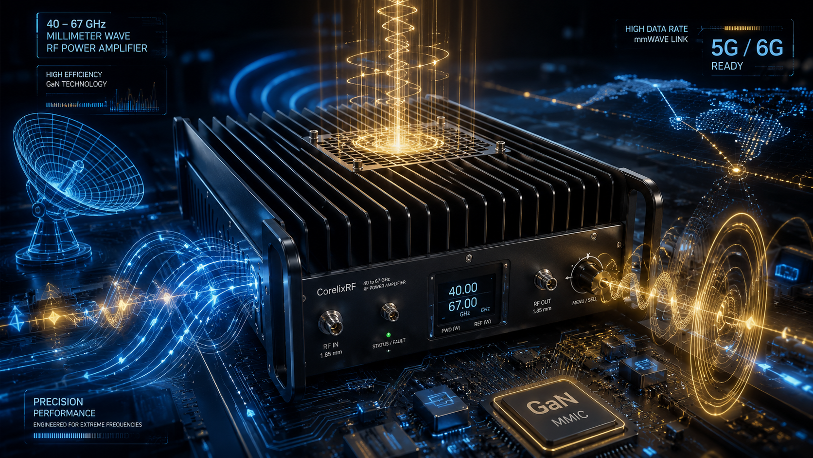
At 40-67 GHz, amplifier selection becomes part RF engineering, part mechanical discipline, and part measurement planning. A 2 W mmWave RF amplifier can be exactly the right tool for high-frequency test systems, but only when the surrounding setup is ready for 1.85 mm interfaces, careful connector handling, forced-air cooling, controlled gain, and repeatable measurements. The CRF-PA-40000M67000M-2W is CorelixRF’s relevant platform here: 40 to 67 GHz coverage, 2 W rated RF output power, 30 dB minimum small-signal gain, up to 15 dB gain control, 1.85 mm-F input/output, RS485 control, AC 220 V supply, and a small-unit forced-air-cooled form factor.
Use this guide as a selection comparison. It is not trying to make every project choose the same amplifier. It is meant to help engineers decide when a compact millimeter-wave amplifier is the right fit and when the project should ask CorelixRF for a custom review.
Choose This Type of Amplifier When the Lab Needs Frequency Reach
The obvious reason to select this model is coverage: 40-67 GHz. That range can support mmWave component validation, communication experiments, radar-related test work, high-frequency front-end evaluation, and controlled RF output paths. It reaches beyond many microwave amplifier platforms while staying in a coaxial 1.85 mm interface environment.
If the test plan only needs a few lower microwave points, a lower-frequency RF power amplifier may be more practical. If the test plan genuinely covers Q/V-band-adjacent work, then 40-67 GHz coverage becomes the primary value.
Choose It When 2 W Is Useful, Not Just Impressive
The 2 W rating matters when the lab needs more than a driver amplifier but does not need a very high-power V-band rack system. This level can support device testing, subsystem validation, path-loss compensation, and antenna or fixture work where stable mmWave output is more important than maximum power.
The datasheet lists +/-8 dB gain flatness and -60 dBc spurious performance. Ask for measured data at your actual frequency points, especially if the test must compare behavior across a wide sweep. CorelixRF’s RF testing and validation resource is relevant because the measured result depends heavily on source, adapters, cable, load, and instrumentation.
Choose It Only If the Interface Plan Is Ready
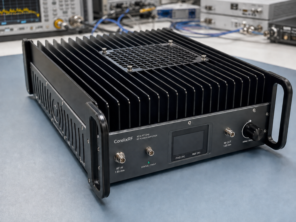
The amplifier uses 1.85 mm female input and output connectors. That single fact can decide whether the lab is ready. Confirm compatible cables, torque tools, calibration kits, adapters, loads, and measurement equipment before the amplifier arrives. Poor connector handling at these frequencies can create repeatability problems that look like amplifier problems.
State the reference plane for measurement. If the output goes through adapters, waveguide transitions, probes, or antennas, include them in the RFQ. A good mmWave purchase request describes the entire path, not only the amplifier.
Choose It When Control and Protection Matter
The CRF-PA-40000M67000M-2W includes RS485 control, real-time temperature monitoring, real-time current monitoring, optional forward/reverse power monitoring, optional input power detection, alarm/fault protection, over-temperature protection, over-drive protection, over-voltage protection, and VSWR protection.
That is useful in an automated high-frequency lab. Gain control over a 15 dB range can help tune output without repeatedly changing the source chain. Protection and monitoring can help identify mismatch, overdrive, or thermal issues before they become hardware failures.
Do Not Choose It Blindly for Mechanical Fit
The datasheet describes the mechanical form factor as a small unit, with final weight per configuration. It also lists forced-air cooling and 0 to +50 degrees C operation. Before selection, confirm physical envelope, connector orientation, airflow direction, mounting surface, service access, warm-up expectations, and cable bend constraints.
For a compact mmWave setup, mechanical convenience can turn into measurement pain if cables are forced into poor bends or connectors are hard to torque correctly. Send those constraints through CorelixRF Contact before quotation.
Final Selection Rule
Select the CRF-PA-40000M67000M-2W when the project needs 40-67 GHz coverage, 2 W output, 1.85 mm coaxial interfaces, RS485 control, forced-air cooling, and a compact GaN SSPA platform. Ask for a custom RF amplifier review when the project needs different connectors, a different package, special monitoring, specific acceptance data, or a system-level integration discussion.
Questions for the Test Engineer
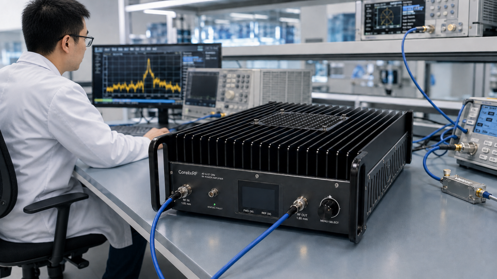
Before the RFQ is sent, ask the test engineer five concrete questions. What frequency points will be measured? Where is the calibration reference plane? What source power will reach the amplifier input? What load, antenna, or fixture sits after the output connector? What data will decide pass or fail?
Those answers matter more at 40-67 GHz than they do in many lower-frequency systems. A small adapter change can shift measured loss. A worn connector can create repeatability problems. A poor load can trigger protection or distort output readings. Including the measurement plan in the inquiry gives CorelixRF a better chance to recommend the right standard amplifier, accessory path, or project-specific adjustment.
FAQ
What is the primary keyword?
The primary keyword is 40-67 GHz 2W mmWave RF amplifier.
What connector type is listed?
The datasheet lists 1.85 mm female RF input and output connectors.
What gain is specified?
The amplifier provides 30 dB minimum small-signal gain with up to 15 dB gain control.
Why is measurement planning important?
At 40-67 GHz, adapters, cables, connector torque, calibration reference plane, and load behavior can strongly affect measured performance.
When should buyers request a custom review?
Request a custom review when connector, mechanical, control, cooling, monitoring, or acceptance-test needs differ from the standard platform.