
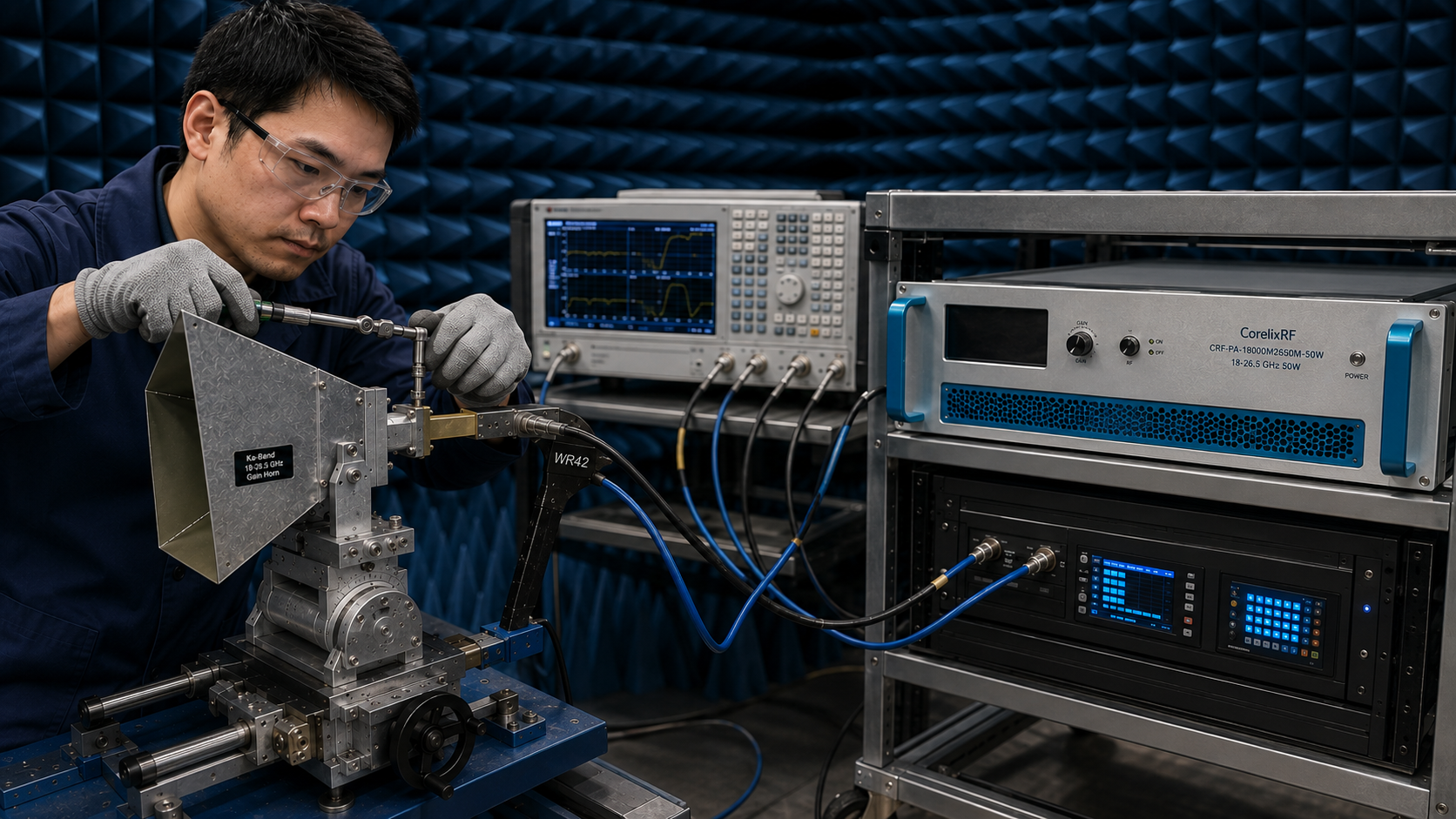
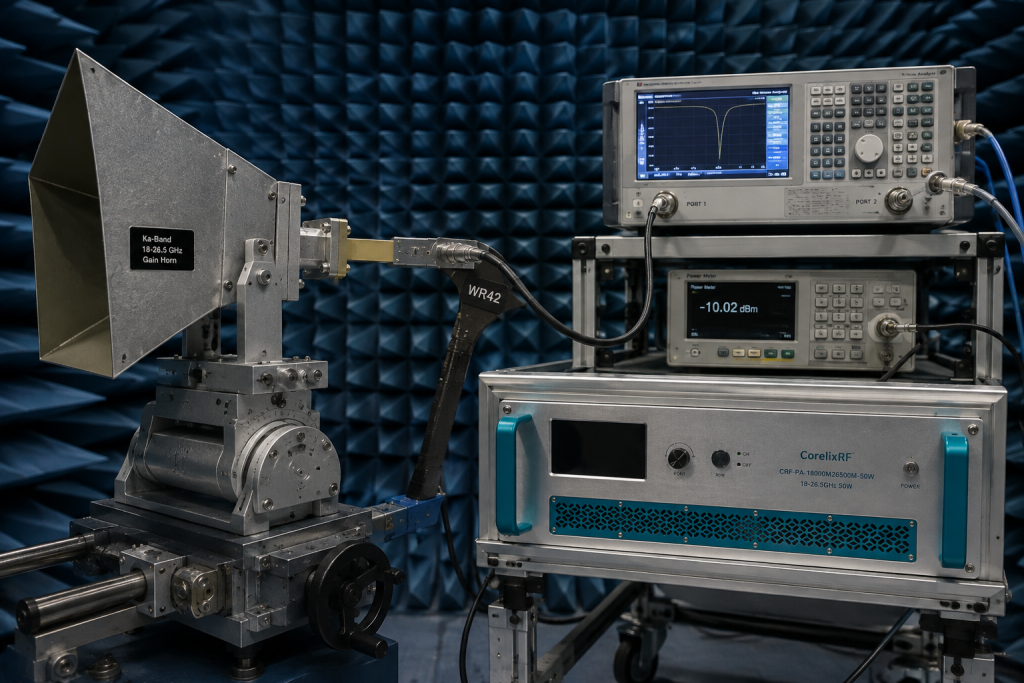
A gain horn antenna mount is not just a mechanical bracket. In a Ka-band amplifier setup, the mount controls pointing repeatability, waveguide stress, cable clearance, and how safely engineers can move between calibration, load testing, and radiated evaluation. This article uses CorelixRF model CRF-PA-18000M26500M-50W as the technical reference point and keeps the discussion within lawful engineering, laboratory, procurement, and controlled integration contexts.
For internal navigation, the draft links readers to CorelixRF resources for gain horn antenna mounts, Ka-band RF amplifier, high-frequency capability, RF power amplifier platform, and CorelixRF engineering team. The closing button sends qualified RFQs to Contact CorelixRF.
What Should Engineers Know About gain horn antenna mounts?
Gain horn antenna mounts searches usually come from engineers or buyers who already know the application area but still need a practical way to qualify hardware. The page should answer three questions quickly: what RF band is relevant, what amplifier class is realistic, and what details must be confirmed before quotation.
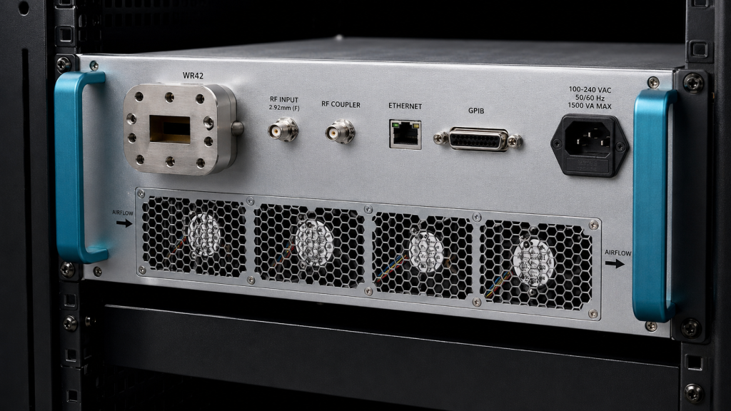
For CRF-PA-18000M26500M-50W, the source specification lists 18-26.5 GHz frequency coverage, 50 W saturated output power; 20 W minimum P1 output power, 47 dB min. small-signal or rated gain, +/-5 dB gain flatness, 2.92 mm-F input, WR42 output, and 2.92 mm-F coupler port, and Ethernet and GPIB control. The amplifier is described as a solid-state RF power amplifier platform for test and measurement instrumentation, communication systems, RF interference or EW system-level testing, and aerospace control. Those application terms should be presented as engineering contexts, not as claims of certification, field deployment, or guaranteed suitability.
Core Specification Review
| Review item | CRF-PA-18000M26500M-50W reference value |
|---|---|
| Frequency range | 18-26.5 GHz |
| Output power | 50 W saturated output power; 20 W minimum P1 output power |
| Gain | 47 dB min. |
| Gain flatness | +/-5 dB |
| RF interfaces | 2.92 mm-F input, WR42 output, and 2.92 mm-F coupler port |
| Control interface | Ethernet and GPIB |
| Cooling and form factor | forced-air 478 x 432 x 132 mm configuration |
| Power supply | AC 220 V +/-10%, 50/60 Hz; <=700 W input |
| Protection and monitoring | over-temperature, over-drive / high-VSWR, over-voltage, over-current, and VSWR alarm functions |
This table is useful because procurement teams often compare amplifier options by frequency and watts first, while system engineers need to check the rest of the interface. Connector format, cooling method, remote-control protocol, input drive limit, load mismatch behavior, and monitoring access can all determine whether a design is easy to integrate or expensive to debug.
How This Keyword Should Shape the Page
The landing page for gain horn antenna mounts should not read like a generic product list. It should open with the application problem, explain the RF path, then show the amplifier selection criteria that reduce risk. A strong page structure would include a short answer section, a specification table, a use-case fit section, an integration checklist, FAQ content, and a clear RFQ CTA.
For this keyword, the article should naturally mention the search term in the headline, first paragraph, at least one H2, the FAQ, and the CTA area. The term should not be repeated in every paragraph. Search intent is narrow, so the page should be specific, technical, and useful enough for an engineer to keep reading after the first screen.
Integration Questions Before Quotation
Before selecting CRF-PA-18000M26500M-50W or requesting a modified amplifier, CorelixRF should receive the target band, required output power at the load, waveform type, CW or pulsed operation, duty cycle, input drive level, load VSWR expectations, operating temperature, cooling constraints, connector preference, rack or module envelope, and remote-control requirements. If the amplifier will be used in a regulated, defense, aerospace, EMC, or counter-UAS-related environment, the requester should also define the authorized test condition and documentation requirements.
The source specification notes monitoring and alarm features, but final behavior should be reviewed against the project configuration. Optional forward/reverse power monitoring, input detection, GPIB, LAN, RS232, or custom protocol support may depend on the selected model and configuration. That is why a keyword page should drive the reader toward an engineering review rather than promising a one-click universal solution.
Why CorelixRF Specifications Matter for SEO Content
The strongest SEO page is also the safest technical page. It uses exact values from the product specification, avoids invented certifications or customer stories, and explains where the buyer must confirm details. For CRF-PA-18000M26500M-50W, the values above give the page original product-specific substance: frequency range, output power, gain, cooling, connector format, control interface, protection, and monitoring.
Those details help the page compete for long-tail searches because the content answers the real comparison work behind the keyword. A buyer looking for gain horn antenna mounts is not only looking for a phrase match. They are looking for enough evidence to decide whether CorelixRF should be shortlisted for an RFQ.
FAQ
What does gain horn antenna mounts mean in this CorelixRF article?
It refers to an RF amplifier selection topic for authorized engineering, laboratory, procurement, or controlled integration use. The article does not provide operational misuse guidance.
Which CorelixRF model is used as the reference example?
The reference model is CRF-PA-18000M26500M-50W, selected because its frequency range, power level, interfaces, and protection features fit the keyword’s likely engineering intent.
What are the key RF specifications to confirm?
Confirm 18-26.5 GHz frequency coverage, 50 W saturated output power; 20 W minimum P1 output power, 47 dB min. gain, gain flatness, RF connectors, control interface, cooling, input drive level, load match, duty cycle, and required test data.
Can CorelixRF customize the amplifier configuration?
The source specifications note optional monitoring and project-specific interface support where applicable. Final customization depends on frequency, power, mechanical, control, and documentation requirements.
What should I send with an RFQ?
Send the target frequency range, output power, waveform, duty cycle, drive level, connector preference, cooling constraints, control interface, operating environment, and any compliance or documentation needs.