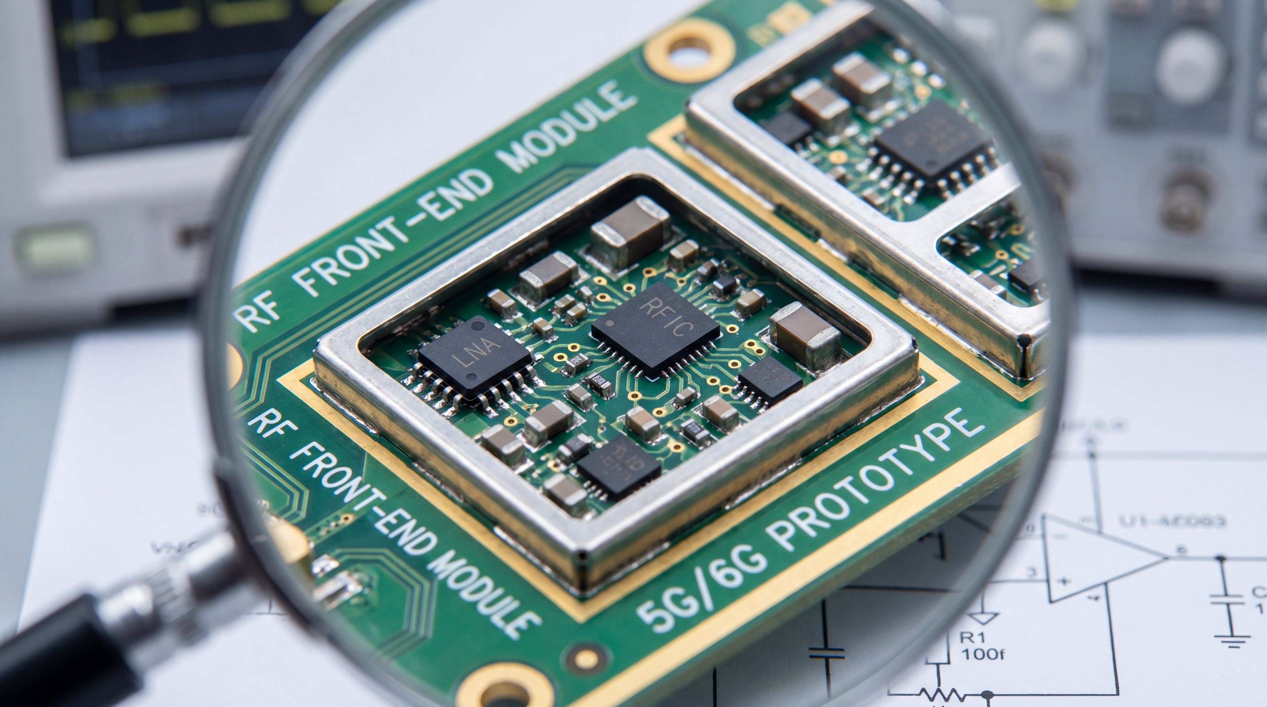
The core principle of Low Noise Amplifier design is to amplify extremely weak signals while adding the absolute minimum amount of internal noise to the system. You face a constant battle against electromagnetic interference and thermal noise that can bury your critical data. This degradation threatens the reliability of your mission-critical satellite or medical systems, leading to catastrophic communication failures. Implementing advanced design principles within modern RF Front-End Platforms ensures your receiver maintains crystal-clear integrity and maximum sensitivity in any environment.
What is a Low Noise Amplifier and why is it critical?
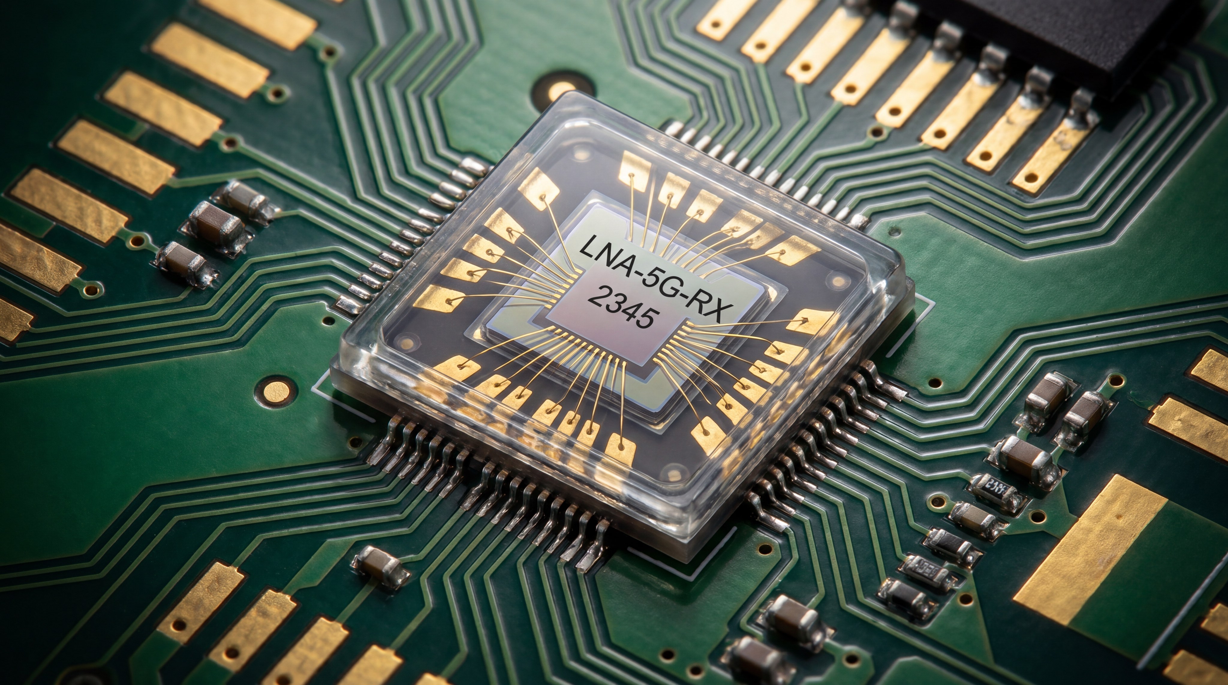
A Low Noise Amplifier is the first active component in a receiver chain designed to boost weak antenna signals without corrupting the signal-to-noise ratio. You rely on this component to set the sensitivity floor for the entire electronic system.
The Role in the Receiver Chain?
The position of the amplifier at the very start of your signal path dictates the performance of every downstream component. Because the first stage’s noise is amplified by all subsequent stages, its purity is non-negotiable.
Here is the deal:
- Sets the system noise floor.
- Determines overall sensitivity.
- Protects signal integrity.
Enhancing Signal Sensitivity?
In long-distance telemetry, the signal arriving at your antenna is often just a few microvolts. The design focus here is on maximizing the Signal-to-Noise Ratio (SNR) rather than raw power output for your High Frequency Capability needs.
Look:
- Detects microvolt-level signals.
- Increases operational range.
- Reduces data packet loss.
Key Takeaway: A Low Noise Amplifier serves as the primary gatekeeper of system sensitivity, dictating the minimum signal level your receiver can successfully process.
| Metric | Importance | Target Goal |
|---|---|---|
| Sensitivity | Critical | Maximum SNR |
| Noise Figure | Primary | < 1.0 dB |
| Position | Front-End | First Stage |
The effectiveness of your receiver is almost entirely dependent on the quality of this initial amplification stage.
How does Noise Figure impact amplifier performance?
The noise figure represents the degradation of the signal-to-noise ratio caused by the amplifier’s own internal components. You must keep this value as low as possible to ensure that the data remains distinguishable from background hiss.
Calculating the Noise Floor?
The noise floor represents the lowest limit of signal detection within your specific hardware environment. By utilizing components with low internal thermal agitation, you can push this floor lower to see signals from further distances.
The best part?
- Defines detection limits.
- Influenced by bandwidth.
- Affected by temperature.
Minimizing Thermal Noise?
Thermal noise is a function of temperature and the bandwidth of your specific application. Advanced designs often utilize specialized semiconductor materials to achieve superior performance at higher frequencies.
Here is the deal:
- Uses GaN or SiGe materials.
- Reduces electron agitation.
- Maintains SNR at high heat.
Key Takeaway: Minimizing the noise figure is the most vital step in preserving the integrity of low-amplitude signals across your receiver.
| Component | Noise Impact | Design Focus |
|---|---|---|
| Input Transistor | High | Low-noise biasing |
| Passive Parts | Moderate | High Q-factor |
| Matching Network | Moderate | Low insertion loss |
Lowering your noise figure directly translates to an increased communication range and higher data throughput.
Why is high gain essential in a Low Noise Amplifier?
Ensuring high gain in a Low Noise Amplifier is a core requirement for Custom RF Development projects to overcome downstream interference. Gain is necessary to mask the noise contribution of subsequent stages like mixers and filters.
Overcoming Downstream Noise?
According to Friis’s formula, the noise contribution of the second and third stages is divided by the gain of the first stage. Therefore, high initial gain effectively “hides” the noise of the rest of your system.
Think about it:
- Neutralizes mixer noise.
- Protects total system NF.
- Improves signal strength.
Gain Flatness Across Bandwidth?
For wideband applications, it is not enough to have high gain if it fluctuates wildly across frequencies. Your gain must be flat across the entire operating range to avoid distorting the frequency response of your signal.
But wait, there’s more:
- Prevents signal distortion.
- Ensures consistent response.
- Critical for SDR systems.
Key Takeaway: High gain is a strategic maneuver to neutralize the noise of the entire receiver system while boosting weak inputs.
| Gain Parameter | Range | Objective |
|---|---|---|
| Typical LNA Gain | 10dB – 30dB | SNR Protection |
| Flatness | ±0.5dB | Signal Fidelity |
| Stability | High | Prevents Oscillation |
Strategic gain distribution ensures that your signal remains well above the system’s internal noise floor at every stage.
How do we manage power consumption in RF designs?
Power consumption must be balanced against gain and noise requirements, especially in battery-operated or portable systems. Efficient power management ensures your device does not overheat, which would otherwise increase thermal noise.
Balancing Gain and Current?
Higher bias currents generally lead to higher gain and lower noise, but they drain your power reserves faster. You must find the “sweet spot” where performance is maximized without exceeding your system’s power budget.
The bottom line:
- Optimizes battery life.
- Controls heat generation.
- Maintains gain levels.
Low-Voltage Operation?
Modern mobile and UAV platforms demand amplifiers that operate efficiently at very low voltages. This requires you to use specialized transistors that provide high transconductance even at low current levels.
The kicker:
- Enables portable use.
- Reduces thermal stress.
- Supports IoT devices.
Key Takeaway: Efficient power management prevents thermal runaway and extends the operational life of your portable RF systems in the field.
| Power Metric | Constraint | Solution |
|---|---|---|
| Current Draw | Battery Life | Low-power biasing |
| Heat Output | Noise Level | Thermal modeling |
| Voltage Supply | Integration | LDO regulation |
Optimization of power consumption allows for high-performance amplification in space-constrained and energy-limited environments.
What role does selectivity play in a Low Noise Amplifier?
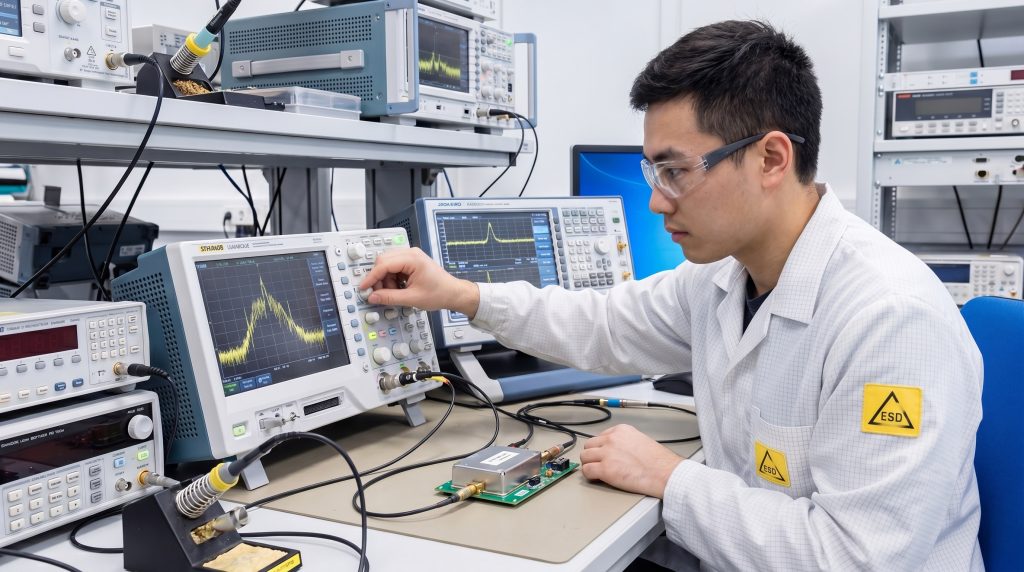
Selectivity within a Low Noise Amplifier is verified through rigorous RF Testing & Validation to ensure interference rejection. It is the ability of your amplifier to focus only on the desired frequency band while ignoring out-of-band noise.
In-Band Signal Focus?
In a crowded electromagnetic environment, an amplifier without selectivity would amplify every signal it sees. This could saturate your receiver with unwanted noise and “ghost” signals that disrupt your data.
Here is the deal:
- Targets specific bands.
- Rejects out-of-band noise.
- Prevents signal overlap.
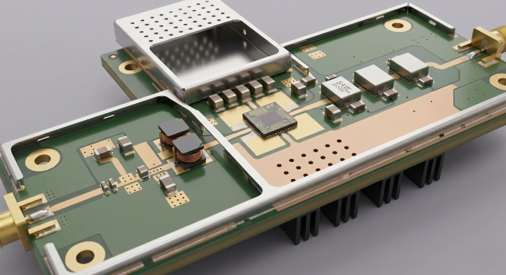
Filtering and Tuning?
Integrating bandpass filters or resonant matching networks allows your amplifier to act as a pre-selector for the system. This ensures only relevant data enters the processing chain, which improves your overall efficiency.
The best part?
- Uses SAW or BAW filters.
- Sharpens frequency edges.
- Improves signal purity.
Key Takeaway: Selectivity protects your receiver from interference and saturation by filtering out unnecessary electromagnetic clutter before it reaches the mixer.
| Feature | Function | Result |
|---|---|---|
| Bandpass Filter | Rejection | Signal purity |
| Resonant Match | Frequency tune | Better sensitivity |
| High Q-Factor | Sharp roll-off | Interference immunity |
Precision selectivity ensures that your receiver chain remains dedicated to the intended signal, even in high-interference zones.
How does temperature affect amplifier sensitivity?
Temperature fluctuations can drastically alter gain and noise characteristics, making thermal management a critical design pillar. You must account for environmental heat to maintain consistent performance in outdoor or industrial settings.
Temperature-Compensated Biasing?
As temperature increases, the gain of most transistors decreases while the noise figure inevitably rises. To counter this, you use compensation circuits that adjust the current to keep your performance stable.
Look:
- Stabilizes gain levels.
- Adjusts bias current.
- Prevents performance drift.
Thermal Modeling and Dissipation?
Efficient heat sinking and mechanical design are necessary to pull heat away from sensitive semiconductor junctions. Even a small increase in junction temperature can degrade your signal-to-noise ratio significantly.
The deal is:
- Uses thermal pads.
- Employs heat sinks.
- Prevents thermal noise.
Key Takeaway: Temperature stability ensures that your receiver performance remains consistent whether operating in arctic or desert conditions.
| Thermal Factor | Impact | Mitigation |
|---|---|---|
| High Temp | Higher Noise | Heat sinks |
| Low Temp | Gain Drift | Active compensation |
| Fluctuations | Phase Shift | Thermal modeling |
Robust thermal management is the difference between a reliable field-deployed system and one that fails under environmental stress.
Why is stability vital for a Low Noise Amplifier?
Maintaining unconditional stability in a Low Noise Amplifier is standard across every standard-platform design we offer. Stability refers to the amplifier’s resistance to self-oscillation across all possible load conditions.
Preventing Parasitic Oscillations?
If an amplifier becomes unstable, it can turn into an oscillator, generating its own signal that drowns out your actual input. This is often caused by unintended feedback paths within your circuit layout.
Think about it:
- Eliminates internal hum.
- Prevents signal loss.
- Ensures reliable output.
Stability Circles and S-Parameters?
You should use S-parameter analysis and stability circles during the design phase to ensure the amplifier remains stable. This is especially important when connecting to antennas with a high Voltage Standing Wave Ratio.
The best part?
- Uses Smith charts.
- Maps load conditions.
- Predicts behavior.
Key Takeaway: Stability prevents the device from becoming a noise source itself, ensuring predictable operation regardless of the antenna load.
| Tool | Purpose | Output |
|---|---|---|
| S-Parameters | Performance map | Stability data |
| Feedback Network | Control | Oscillation suppression |
| Resistor Load | Stabilization | Dampened peaks |
Unconditional stability ensures that your amplifier provides a clean signal regardless of input impedance or environmental changes.
How do we achieve proper impedance matching?
Designing for low noise requires precise impedance matching at both the input and output stages of your circuit. Proper matching ensures maximum power transfer and minimizes reflections that cause signal loss or instability.
Input Matching for Noise vs. Power?
A unique challenge is that the input impedance for the lowest noise is rarely the same as the impedance for highest power. You must use a “noise matching” approach to find the best compromise for your system.
Look:
- Balances SNR and Power.
- Uses Gamma-Opt points.
- Reduces input loss.
Transmission Lines and Lumped Elements?
At microwave frequencies, you move away from simple inductors toward transmission lines and microstrip stubs for matching. These tools allow you to transform impedance with extreme precision at high speeds.
Here is the deal:
- Uses microstrip stubs.
- Adjusts phase shift.
- Optimizes power flow.
Key Takeaway: Proper matching balances the conflicting requirements of minimum internal noise and maximum signal power transfer.
| Component | Role | Frequency Suitability |
|---|---|---|
| Inductors | Phase adjustment | Low – Medium |
| Capacitors | DC blocking | Low – Medium |
| Microstrip | Impedance shift | High / Microwave |
Precision matching is the key to extracting every bit of performance from your amplifier’s internal semiconductor devices.
What determines the linearity of a Low Noise Amplifier?
The linearity of a Low Noise Amplifier is critical when integrating Pulsed RF Amplifiers into complex systems. Linearity is your amplifier’s ability to handle stronger signals without distorting the data they carry.
Understanding Compression Points?
When an input signal becomes too strong, the amplifier saturates, and the output no longer increases linearly. You measure this limit using the 1dB compression point (P1dB) to define your operating range.
Think about it:
- Defines power limits.
- Prevents saturation.
- Ensures signal truth.
Intermodulation Distortion?
In environments with multiple signals, non-linearities can cause signals to mix and create unwanted “ghost” frequencies. High linearity ensures these artifacts remain below your noise floor and do not interfere.
But wait, there’s more:
- Reduces ghost signals.
- Improves signal purity.
- Critical for multi-tone.
Key Takeaway: Linearity prevents signal distortion and ensures your system can handle a wide range of signal strengths without failure.
| Metric | Significance | Desired State |
|---|---|---|
| P1dB | Saturation limit | Higher is better |
| IP3 | Intermodulation | Maximized |
| Dynamic Range | Flexibility | Wide |
Maintaining high linearity allows your receiver to stay sensitive to weak signals even when a strong interferer is nearby.
How is noise source isolation achieved effectively?
You must protect the amplifier from internal and external noise sources to maintain its high sensitivity level. Isolation techniques prevent unwanted energy from leaking into your signal path and raising the noise floor.
Layout and Shielding?
Physical separation and metallic shields are essential to prevent electromagnetic interference from reaching your LNA input. You must isolate the sensitive front-end from digital circuits and power supplies.
The bottom line:
- Blocks external EMI.
- Isolates digital noise.
- Shields signal lines.
Minimizing Ground Loops?
Improper grounding can introduce hum and noise that ruins your amplifier’s performance. Using a single-point ground or a robust ground plane is critical for isolating low-noise stages from the rest.
Look:
- Reduces circuit hum.
- Stabilizes ground.
- Prevents noise loops.
Key Takeaway: Noise isolation creates a “quiet room” for your signal, ensuring external interference does not degrade high-performance hardware.
| Technique | Method | Benefit |
|---|---|---|
| EMI Shielding | Physical box | Blocks external noise |
| Ground Plane | PCB design | Reduces loop noise |
| Decoupling | Cap filtering | Power supply purity |
Rigorous isolation protocols ensure that the hard-won noise performance of your internal components is not compromised by the surrounding environment.
Frequently Asked Questions
Can I use a standard power amplifier as a Low Noise Amplifier?
No, because power amplifiers are designed for high output and efficiency, which results in a much higher noise figure. You specifically need a specialized Low Noise Amplifier at the front end to preserve the signal-to-noise ratio of your incoming data.
Can I integrate a Low Noise Amplifier directly onto an antenna?
Yes, this is the ideal configuration because it minimizes the length of the transmission line between the source and the amplifier. Doing this reduces signal loss and prevents the noise floor from rising due to cable attenuation.
Can I identify if my Low Noise Amplifier is saturating easily?
You can identify saturation by monitoring the output gain; if the gain drops by 1dB compared to the linear expectation as you increase input power, your amplifier has reached its compression limit.
Can I achieve better noise figures using GaN instead of GaAs?
It depends on your frequency; while GaAs often provides the lowest noise figure at extremely high frequencies, GaN is generally superior for high-power handling and robustness in harsh environments.
Can I use Smith charts to optimize my impedance matching?
Absolutely, Smith charts are the best tool for visualizing the trade-off between power matching and noise matching. Most engineers use them alongside simulation software to find the optimal Gamma-Opt point for their design.
Conclusion
Mastering the principles of Low Noise Amplifier design is the only way to ensure your RF systems remain competitive in an increasingly crowded spectrum. By focusing on noise figure minimization, strategic gain, and rigorous isolation, you can solve the problem of signal degradation before it impacts your bottom line. At CorelixRF, our vision is to empower your engineering team with factory-direct, high-performance RF platforms that exceed standard specifications. If you are ready to elevate your receiver’s sensitivity and reliability, contact us today to discuss your custom project requirements.