An RF Power Amplifier is a specialized device that converts low-power radio frequency signals into a higher power output to drive antennas or other RF loads. Many engineering projects suffer from weak signal transmission and high noise floors that degrade critical data integrity. Relying on standard low-power modules often leads to overheating, poor efficiency, and signal clipping, causing costly delays. Investing in high-performance amplification provides the necessary headroom and stability for precision signal delivery across your entire operating band.
What is an RF Power Amplifier and how does it function?
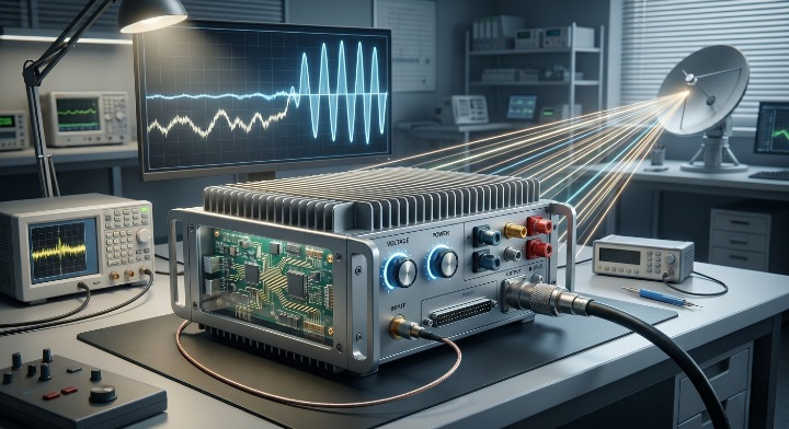
An RF Power Amplifier increases the amplitude of a high-frequency signal while maintaining the signal’s modulation and waveform characteristics. This process typically involves an input stage, an active gain stage using transistors, and an impedance matching network. By utilizing DC power from a supply, the amplifier boosts the signal strength to the levels required for long-distance transmission.
Defining the basic amplification process
The amplification process starts when a weak signal enters the active device where energy is added. High-frequency transistors like GaN or GaAs act as the heart of this system to ensure high efficiency.
Think of it this way:
- Signal input stage
- Gain stage (Active device)
- Impedance matching
- Output power delivery
Key Takeaway: Amplification is the core mechanism that allows signals to bridge long distances without losing fidelity.
| Feature | Audio Power Amp | RF Power Amplifier |
|---|---|---|
| Frequency Range | 20 Hz – 20 kHz | 4 kHz – 170 GHz |
| Main Load | Speakers | Antennas / RF Loads |
| Media Output | Sound Waves | Electromagnetic Waves |
Analysis: High-frequency amplification requires specialized resonant circuits that are not found in standard audio equipment.
Why is an RF Power Amplifier vital for signal range?
An RF Power Amplifier provides the raw wattage necessary to overcome the physical barriers of signal propagation and path loss. Without a dedicated power stage, your signal may not have the strength to reach its destination in complex environments. This is particularly important when your project utilizes broadband solutions that cover multiple octaves.
Driving demanding high-wattage equipment
Dedicated units handle requirements from 20W to over 10kW, which integrated units simply cannot reach. These high power levels are necessary for driving high-gain antennas and managing signal spikes during heavy data transmission.
The truth is:
- Overcoming cable loss
- Driving high-gain antennas
- Managing high-wattage spikes
- Maintaining signal linearity
Key Takeaway: Dedicated units provide the raw power necessary for industrial-grade signal transmission and environmental penetration.
| Factor | Integrated Solution | Dedicated Power Amp |
|---|---|---|
| Max Power | Limited (~100W) | Multi-kW (10kW+) |
| Upgrade Path | Full Replacement | Modular Swaps |
| Heat Management | Shared Enclosure | Dedicated Cooling |
Analysis: Consider the lifetime cost of your system, as modular amps often save money during frequency migration phases.
How does a separate RF Power Amplifier improve purity?
A separate RF Power Amplifier improves spectral purity by isolating the high-power output stage from the delicate low-power processing circuits. Integrated solutions often suffer from internal electromagnetic interference that increases the noise floor of the signal. By separating these components, you ensure that the amplified output remains clean and free from harmonic distortion.
Eliminating circuitry compromise and noise
Internal isolation in a separate power amp leads to a much better signal-to-noise ratio (SNR) for your receiver. Physical separation prevents high-voltage draws from corrupting the delicate signals in your pre-gain stages.
Here is the kicker:
- Physical circuit separation
- Shielding from EM interference
- Dedicated voltage regulation
- Reduced thermal noise
Key Takeaway: Removing the pre-amp from the power stage prevents delicate signals from being corrupted by high-voltage draws.
| Performance Metric | Integrated Amp | Separate Power Amp |
|---|---|---|
| Gain Flatness | Medium | High / Precision |
| Noise Isolation | Moderate | Excellent |
| Signal Purity | Basic | Lab-Grade |
Analysis: When working in microwave or millimeter-wave bands, separate components are almost always required for signal stability.
When should you choose a pulsed RF Power Amplifier?
A pulsed RF Power Amplifier is the ideal choice for applications like radar and EMC testing where massive peak power is required for short durations. These pulsed systems allow you to reach power levels that would otherwise destroy the hardware if operated continuously. They are designed to manage extreme thermal stress during the “on” cycle while cooling during the “off” cycle.
Understanding pulse for radar and EMC
Pulsed modes allow for higher output levels than the physical hardware could survive in a continuous state. This makes them perfect for target detection and simulating intense electromagnetic environments without excessive energy consumption.
Why does this matter?
- High-peak power (kW range)
- Lower thermal stress
- Radar target detection
- EMC immunity testing
Key Takeaway: Pulsed modes allow for higher output levels than the physical hardware could survive in a continuous state.
| Mode | Peak Power | Duty Cycle | Primary Application |
|---|---|---|---|
| Pulsed | Extremely High | Low (e.g., 10%) | Radar / Scanning |
| CW | Stable / Rated | High (100%) | Comms / Streaming |
Analysis: You must calculate your specific duty cycle before selection to avoid triggering internal thermal protection.
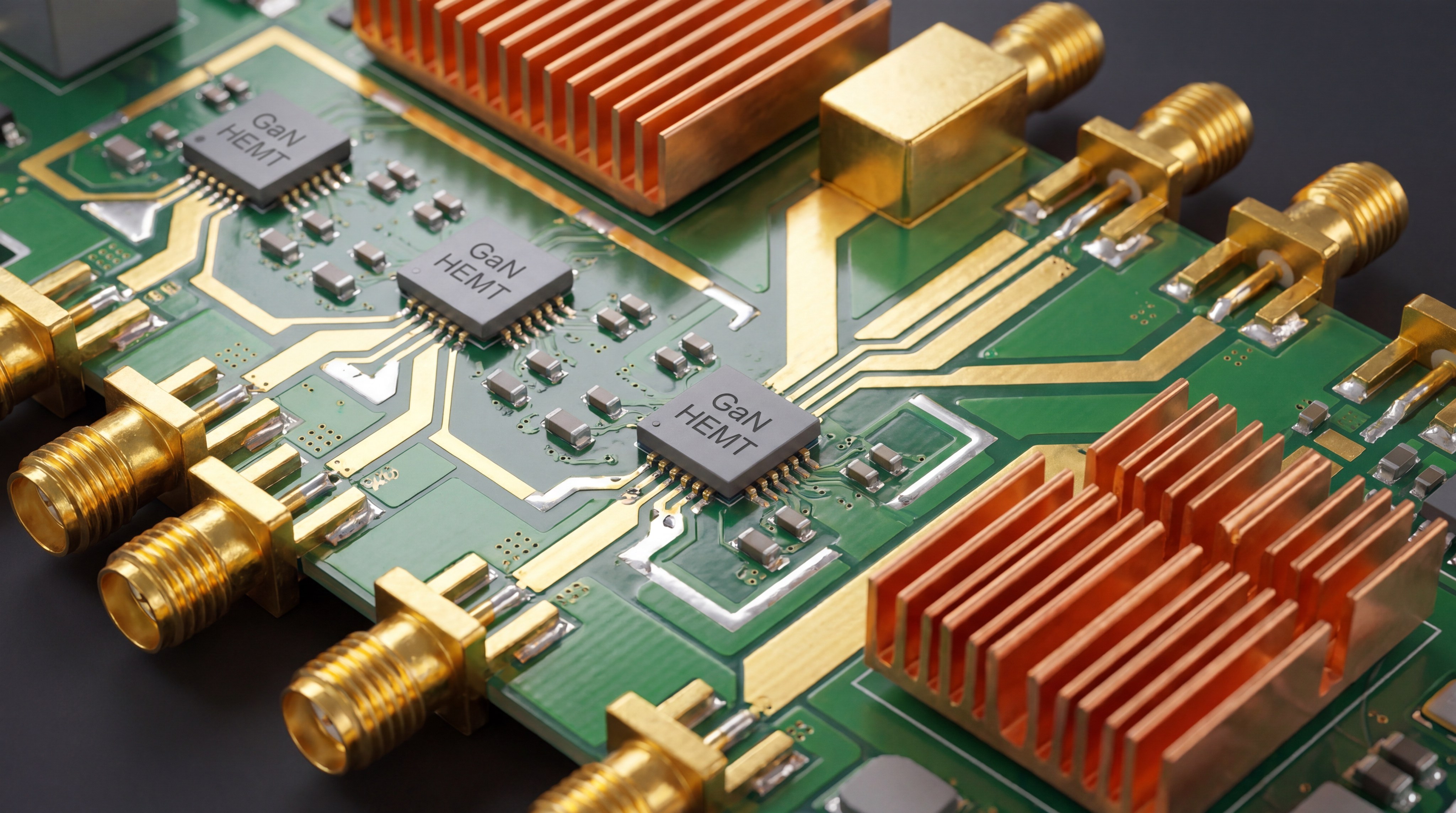
Why does GaN technology matter in an RF Power Amplifier?
A modern RF Power Amplifier often utilizes Gallium Nitride (GaN) technology to achieve superior power density and efficiency. GaN transistors can operate at much higher voltages and temperatures than traditional silicon-based components. This allows for smaller, more lightweight modules that deliver significantly more power for airborne or portable applications.
Achieving higher efficiency and power density
GaN surpasses silicon-based units in power-to-size ratios, making it the modern standard for compact high-wattage systems. It provides a higher breakdown voltage and much greater Power Added Efficiency (PAE).
Simply put:
- Higher breakdown voltage
- Greater Power Added Efficiency
- Reduced module footprint
- Wider operating bandwidths
Key Takeaway: GaN is the modern standard for high-wattage amplifiers that need to remain portable or compact.
Improving thermal management in small frames
The ability of GaN transistors to operate at higher temperatures without losing performance is a major engineering advantage. Superior thermal conductivity leads to longer equipment life and less downtime in harsh environments.
Surprisingly enough:
- High thermal conductivity
- Reliable high-temp operation
- Simplified cooling needs
- Extended MTBF (Reliability)
Key Takeaway: Superior thermal properties lead to longer equipment life and less downtime in harsh environments.
| Material | Efficiency | Power Density | Frequency Limit |
|---|---|---|---|
| Silicon (LDMOS) | Moderate | Low | < 4 GHz |
| GaN | High | High | > 100 GHz |
Analysis: For airborne or battery-powered systems, always prioritize GaN-based architectures to maximize runtime and reduce weight.
Can an RF Power Amplifier handle multi-kW lab testing?
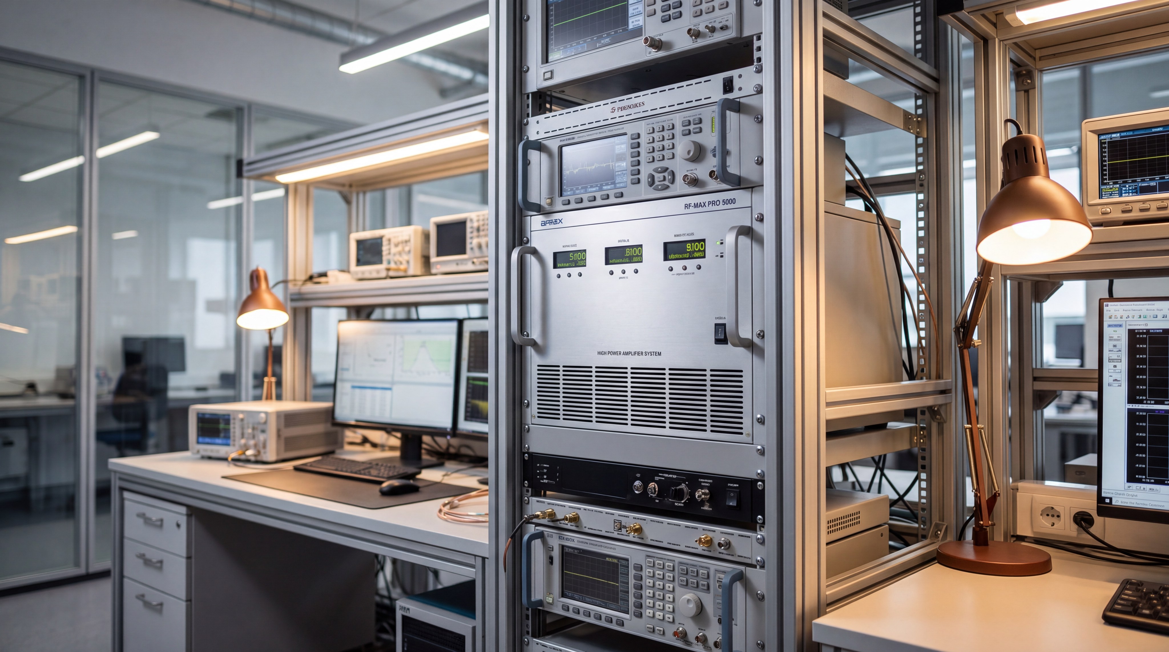
An RF Power Amplifier designed for laboratory use is specifically built to handle multi-kW loads during rigorous EMC testing. These systems often come in rack-mount configurations with advanced liquid or forced-air cooling to maintain stability over long test cycles. They provide the repeatable, high-power output required to validate equipment against international standards.
Managing power from 20 W to 10 kW+
Industrial requirements range from small 20W modules to massive 10kW+ systems used in satellite and radar research. High-power testing requires advanced thermal management to dissipate the heat generated by such high energy density.
Let’s look closer:
- Module-level 20W units
- Rack-mount 500W systems
- Multi-kW pulsed radar
- High-power EMC testing
Key Takeaway: The power density in multi-kW RF systems requires advanced thermal and mechanical engineering for safe operation.
| Spec | Home Audio Amp | Industrial RF Amp |
|---|---|---|
| Bandwidth | Fixed (20kHz) | Wide / Multi-octave |
| Connector Type | RCA / Speaker Wire | SMA / N / Waveguide |
| Efficiency Focus | Sound Fidelity | Power Added Efficiency |
Analysis: Determine your peak power requirements early to ensure your thermal management system can handle the dissipated heat.
How do frequency bands affect your RF Power Amplifier?
Your choice of RF Power Amplifier is dictated by whether you need broadband versatility or narrowband efficiency. Operating in high-frequency bands like Ku or Ka-band requires precision micro-assembly that is not necessary for lower VHF or UHF frequencies. Selecting the right frequency range ensures you don’t lose power to unnecessary filtering or mismatch.
Reaching microwave and millimeter-wave bands
High-frequency projects operating in the 18 GHz to 110 GHz range demand extreme precision in manufacturing. These bands are essential for 5G/6G validation, satellite uplinks, and advanced atmospheric monitoring.

But wait, there’s more:
- SATCOM Ku/Ka bands
- 5G/6G validation
- Short-range radar
- Atmospheric monitoring
Key Takeaway: High-frequency bands demand precision manufacturing and micro-assembly techniques to maintain signal integrity.
| Range | Common Use | Complexity Level |
|---|---|---|
| < 6 GHz | UAV / Communications | Standard |
| 18 – 40 GHz | Satellite / 5G | Advanced |
| > 110 GHz | mmWave / Research | Specialized |
Analysis: Broadband platforms provide the best growth potential if your application requires future-proofing for higher bands.
Is internal protection crucial for your RF Power Amplifier?
Internal protection circuits in an RF Power Amplifier prevent catastrophic failure caused by antenna mismatches or overheating. Professional-grade amplifiers monitor the Voltage Standing Wave Ratio (VSWR) to detect when power is being reflected back into the unit. Without these protections, an accidental disconnect or damaged cable could lead to immediate hardware destruction.
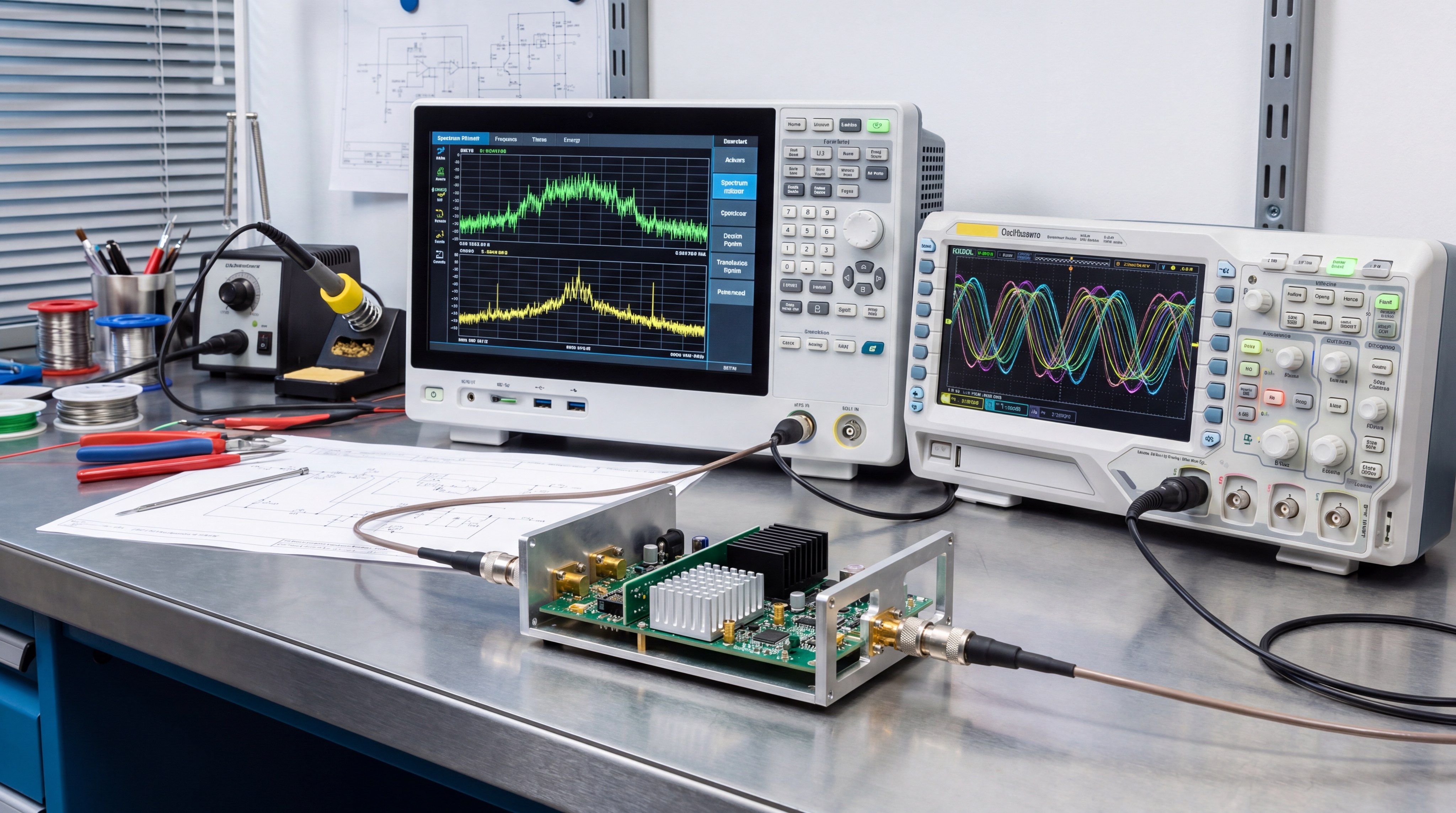
Validating VSWR and harmonic distortion
High-quality amplifiers include specialized circuits that prevent damage during an antenna mismatch event. They also filter out 2nd and 3rd harmonics to ensure your transmission does not pollute the surrounding spectrum.
Watch out for this:
- VSWR protection ratings
- 2nd and 3rd harmonics
- Spectral regrowth limits
- Spurious emission checks
Key Takeaway: High-quality amplifiers include protection circuits that prevent damage during antenna mismatch and ensure spectral compliance.
| Test Parameter | Standard Requirement | Professional Validation |
|---|---|---|
| Unit Testing | Sampled / Estimated | Individual Test Record |
| Frequency Sweep | Partial | Full Bandwidth |
| Protection | Basic Fuse | Multi-stage VSWR |
Analysis: Always archive your unit-level test data to serve as a baseline for future system performance audits.
How does an RF Power Amplifier integrate with SDRs?
An RF Power Amplifier acts as the heavy-lifting stage for software-defined radios (SDRs) that typically output very low power. You can use an RF configurator to match the gain of the amplifier to the specific output voltage of your SDR platform. This integration allows for highly flexible, software-controlled transmission systems capable of industrial-range communication.
Mastering gain control and impedance matching
A well-matched pair ensures maximum power transfer from the SDR to the antenna with minimal signal reflection. Balancing the signal-to-noise ratio is vital to prevent the amplifier from boosting the noise floor along with the signal.
To put it another way:
- Matching 50 Ohm systems
- Controlling input sensitivity
- Balancing SNR ratios
- Preventing stage distortion
Key Takeaway: A well-matched preamp-amp pair is the foundation of a high-purity RF chain for software-defined applications.
| Component | Signal Level | Primary Goal |
|---|---|---|
| Preamplifier | Low (mV/mW) | Clarity / Selection |
| Power Amplifier | High (Watts/kW) | Strength / Reach |
Analysis: If your source signal is from an SDR, check if the unit’s output voltage is sufficient to drive the amplifier directly.
What documentation ensures your RF Power Amplifier is reliable?
Professional reliability for an RF Power Amplifier is confirmed through unit-level test documentation rather than generic datasheets. You should require data for your specific serial number to verify gain flatness, P1dB compression, and thermal stability. This documentation serves as a performance baseline and ensures the unit meets the mission-critical specs required for field deployment.
Requiring unit-level test documentation
Individual testing ensures that every unit meets the specific requirements of your project before it leaves the factory. Typical datasheets only provide averages, which may not account for the variances in high-frequency hardware.
Demand the data:
- Gain flatness curves
- Measured P1dB compression
- Thermal stability logs
- Full bandwidth sweeps
Key Takeaway: Individual unit testing ensures that every amplifier meets the mission-critical specifications required for reliable deployment.
| Standard | Focus | Application |
|---|---|---|
| ISO 9001 | General Quality | Commercial |
| GJB 9001C | High Reliability | Defense / Military |
| RoHS | Material Safety | Environmental |
Analysis: Verify that your manufacturer provides individual test reports covering gain, power, and VSWR for every serial number.
Conclusion
Investing in a dedicated power amplifier is the most effective way to ensure your RF project meets its performance targets. By separating amplification from signal processing, you gain the power, quality, and flexibility needed for long-term success in the field. Whether you require a standard broadband module or a custom multi-kW system, choosing a manufacturer with verified unit-level data is the first step toward a stable signal. To discuss your specific engineering requirements or request a technical review, please contact us today.
FAQ
Can I use a broadband amplifier for pulsed radar?
Yes, but you must ensure the unit’s thermal management and power stages are rated for high-peak pulses and specific duty cycles.
What’s the best cooling method for high-power systems?
For systems under 500W, forced air is often sufficient; however, multi-kW platforms usually require liquid cooling or large-scale rack fans.
Can I customize the control interface for OEM integration?
Absolutely, as most professional manufacturers support RS232, Ethernet, and TTL custom configurations to match your system’s controller.
What’s the difference between ISO 9001 and GJB 9001C?
ISO 9001 is a global quality standard, while GJB 9001C is a specialized standard focusing on the higher reliability needs of military systems.
Can I get unit-level test data for my specific amplifier?
Yes, professional RF manufacturers provide individual test reports covering gain, power, and VSWR for every serial number delivered.
Use the guide as a direct RFQ starting point
If you already know the band and output target, the next step is to send a complete RFQ: frequency, power, gain flatness, linearity, duty cycle, control, cooling, protection and document requirements. CorelixRF can then match a platform or custom path.
Recommended next step: send the operating band, output power target, duty cycle, load condition, control interface, grounding or thermal limits and required FAT documents. CorelixRF can review this RF power amplifier selection guide requirement against standard RF amplifier platforms, RF front-end options and controlled customization paths.