The basics of power amplifiers center on the conversion of low-level electronic signals into high-energy outputs sufficient to drive a load like an antenna or radar array. In professional RF engineering, a weak signal is more than just a technical glitch; it is a point of failure that can lead to catastrophic data loss, distorted communication, or radar detection gaps. When mission-critical systems in aerospace or industrial testing lack the necessary energy to drive complex loads, the entire infrastructure becomes unreliable. Inefficient amplification generates excessive heat and introduces noise that compromises system integrity and project timelines. High-performance units from a leading RF Power Amplifier manufacturer provide the necessary gain and linearity to ensure every signal reaches its destination with maximum fidelity.
1. What Exactly Defines a Modern Power Amplifier in RF Engineering?
A modern power amplifier is defined as an active component that converts a low-power input signal into a significantly higher-power output to drive a specific load. Within any advanced RF Power Amplifier system, the primary goal is to provide sufficient gain while preserving the original signal’s characteristics. You will find these devices at the final stage of a transmission chain, where they interface directly with antennas or speakers. Their design must account for power efficiency and thermal stability to ensure long-term reliability in the field.
H3: The Core Function of Active Gain Devices
Active gain devices utilize transistors or integrated circuits to increase the amplitude of your input waveform. These components draw power from a DC source and use the input signal to modulate that power into a replica with higher magnitude.
- Transistors (FETs/BJTs)
- Integrated Circuits (ICs)
- MOSFETs
- Vacuum Tubes (in legacy systems)
H3: High-Power Load Driving for Antennas and Systems
Driving a load requires the amplifier to overcome impedance mismatches and deliver stable current or voltage. Without proper matching, you risk signal reflection which can damage the sensitive internal components of the system.
Let’s dive in.
Key Takeaway: Power amplifiers are the muscle of the RF chain, transforming weak control signals into robust transmission energy.
| Feature | Description |
|---|---|
| Primary Goal | Increase signal amplitude and power levels |
| Active Components | Transistors, ICs, and MOSFETs |
| Typical Loads | Antennas, Radar, and Communication arrays |
Selecting the right device requires a balance between gain requirements and the specific impedance of your target load.
2. How Does a Power Amplifier Convert Low-Level Inputs into Outputs?
This conversion process involves a multi-stage transformation that begins with impedance matching at the input and ends with high-energy delivery. Every RF Power Amplifier relies on internal biasing to set the operating point for its active semiconductor stages. You must carefully manage the transition from the pre-amplification stage to the final power stage to avoid introducing unwanted harmonics. Modern engineering techniques ensure that this energy transfer occurs with minimal loss to maximize overall system efficiency.
H3: The Four Stages of Signal Transformation
The journey of a signal typically passes through an input stage, an intermediate gain stage, and a final output stage. Each step is monitored by control circuitry to ensure that the DC bias remains stable under varying loads.
- Input Pre-amplification
- DC Biasing Control
- Power Gain Stage
- Impedance Matching Output
H3: Maintaining Waveform Fidelity and Spectral Purity
Maintaining fidelity means the output signal remains a perfect high-power replica of the original low-level input. Engineering teams focus on reducing intermodulation distortion to ensure that the spectral purity of your transmission is never compromised.
You’ve got to see this.
Key Takeaway: Signal conversion is a precision-guided process of biasing and impedance control that ensures high-power output matches input intent.
| Stage | Main Objective |
|---|---|
| Input | Impedance matching and initial weak signal boost |
| Amplification | Significant power gain through semiconductor biasing |
| Control | Monitoring thermal levels and DC bias stability |
| Output | Final power delivery to the system load |
Conversion efficiency determines how much DC energy is successfully turned into RF power versus wasted as heat.
3. Which Amplifier Classes Are Essential for B2B RF Applications?
Essential classes for B2B applications include Class A, B, AB, and D, each offering a different trade-off between linearity and efficiency. When selecting an RF Power Amplifier, you must determine if your application prioritizes the high fidelity of Class A or the high efficiency of Class D switching. Class AB remains the industry workhorse because it balances moderate efficiency with high-fidelity performance for communication. Understanding these classes allows you to optimize your system for either battery life or maximum signal purity.
H3: Evaluating Class A vs. Class AB for Linearity
Class A amplifiers provide the highest linearity because they conduct current through the entire signal cycle, but they are thermally inefficient. Class AB improves on this by reducing the conduction angle, offering a practical middle ground for professional RF systems.
- Class A: Best linearity, lowest efficiency
- Class B: High efficiency, higher distortion
- Class AB: Balanced performance for B2B
- Class C: Maximum efficiency for pulsed signals
H3: The Efficiency Advantage of Class D Switching
Class D amplifiers utilize pulse-width modulation to switch active devices on and off rapidly, which minimizes power dissipation. This approach is ideal for compact designs where you need to minimize heat while driving significant output levels.
Here is the bottom line.
Key Takeaway: Choosing the right amplifier class is a strategic decision that impacts the thermal management and power consumption of your entire project.
| Class | Efficiency | Linearity | Typical Application |
|---|---|---|---|
| A | Low | High | High-fidelity / low-noise RF |
| AB | Moderate | Moderate/High | Most RF communication systems |
| D | Very High | Low/Moderate | Switching power / portable devices |
The application’s duty cycle and bandwidth requirements usually dictate which amplifier class provides the most reliable long-term solution.
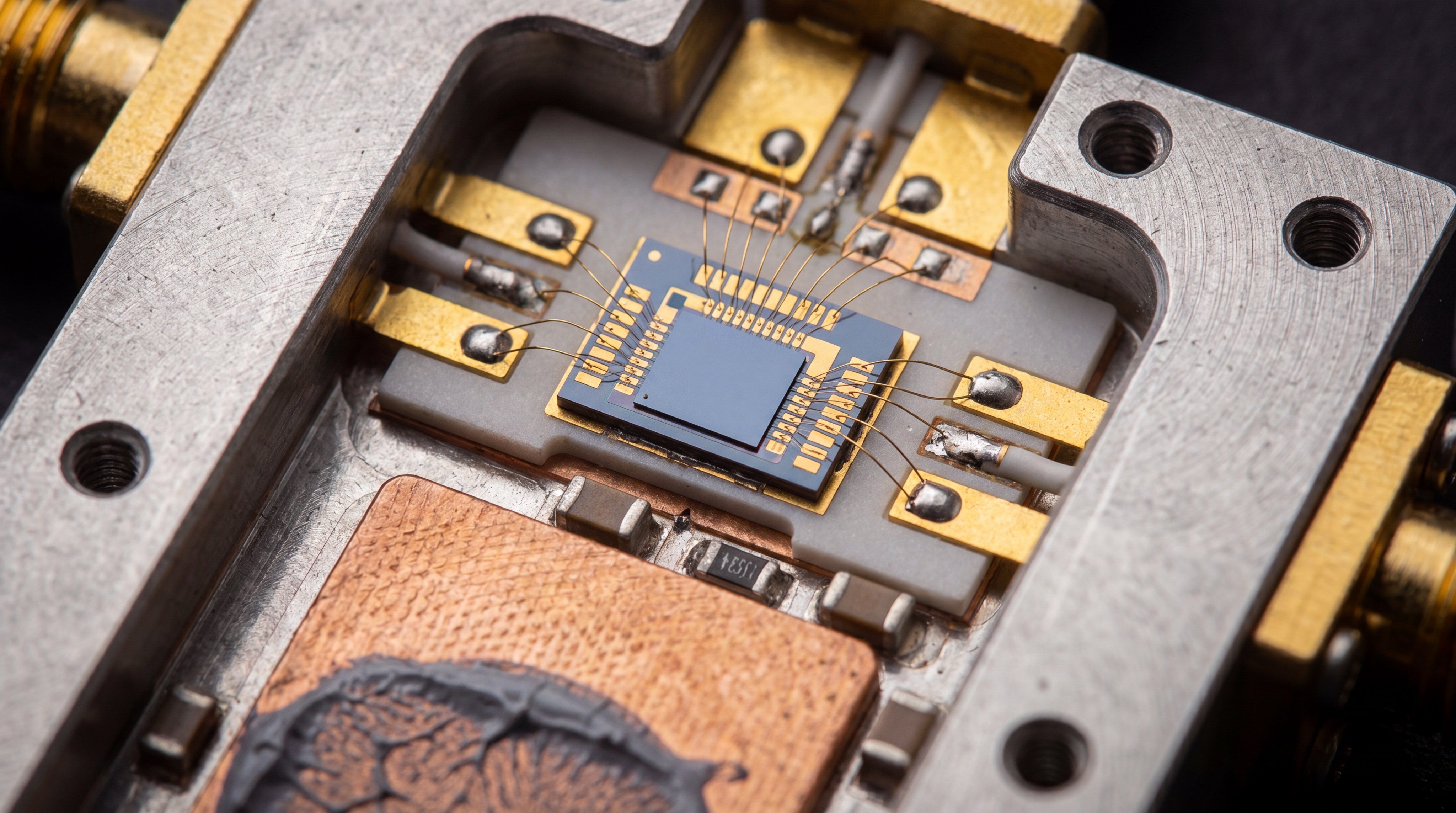
4. Is the Move Toward Solid-State Power Amplifiers Transforming Aerospace?
The transition to solid-state technology is fundamentally transforming aerospace by replacing bulky vacuum tubes with reliable, compact semiconductor modules. Integrating a solid-state RF Power Amplifier into satellite or aircraft systems significantly reduces weight while increasing MTBF (Mean Time Between Failures). You can now achieve higher output densities and broader frequency coverage in platforms that previously required extensive maintenance. This shift enables more complex electronic warfare and long-range communication capabilities across diverse mission profiles.
H3: Satellite Transmissions and Long-Range Reliability
Satellite systems require amplifiers that can operate in harsh environments while overcoming immense atmospheric attenuation. Solid-state units provide the consistent gain needed to maintain stable ground-to-space links over decades of operation without degradation.
- Weight reduction in SATCOM payloads
- Increased thermal stability in vacuum conditions
- Higher reliability over thousands of hours
- Reduced maintenance overhead for ground stations
H3: Electronic Warfare and High-Bandwidth Demands
Modern electronic warfare demands rapid frequency hopping and high-bandwidth jamming capabilities that only solid-state architectures can support. You gain the agility to dominate the electromagnetic spectrum by utilizing the fast switching speeds of GaN and GaAs semiconductors.

Let’s look closer.
Key Takeaway: Solid-state technology is the new standard for aerospace, offering a combination of durability and performance that vacuum tubes cannot match.
| Aerospace Use-Case | Role of Amplifier | Critical Requirement |
|---|---|---|
| SATCOM | Uplink signal boosting | Reliability & Gain |
| Radar | Detection signal power | Peak Power & Linearity |
| Avionics | VHF/UHF Communication | Compactness & Low Noise |
The reduction in physical size and increase in reliability make solid-state platforms the preferred choice for next-generation aerospace infrastructure.
5. What Differentiates an RF Power Amplifier from a Standard Integrated Unit?
The primary difference lies in the specialization of the standalone power amplifier, which focuses exclusively on high-energy output rather than multi-functional processing. While an RF Power Amplifier is designed to provide massive gain for external loads, integrated units often combine pre-amplifiers, filters, and digital processing into one package. You choose standalone units when your system architecture requires customized gain stages or extremely high power levels. This modularity allows for easier upgrades and more precise control over the signal chain’s final output.
H3: Flexibility and Customization in System Architecture
Professional laboratories often prefer modular components because they allow you to swap power stages based on specific project needs. This flexibility is essential when you are testing different antennas or simulating varied electromagnetic environments.
- Independent power scaling
- Easier diagnostic isolation
- Optimized thermal isolation
- Customized filtering options
H3: Dedicated Power Output vs. Multi-Functional Processing
Dedicated amplifiers are optimized for a single task: delivering power with maximum efficiency and minimal noise. Integrated units may save space, but they often compromise on peak power capability or thermal headroom compared to standalone platforms.
The results are clear.
Key Takeaway: Standalone power amplifiers offer the modularity and raw performance necessary for high-stakes industrial and aerospace applications.
| Feature | Standalone Power Amp | Integrated Amplifier |
|---|---|---|
| Complexity | High (Modular) | Low (All-in-one) |
| Customization | Extensive | Limited |
| Power Capability | High to Very High | Moderate |
For mission-critical hardware, the superior performance and serviceability of a dedicated power stage typically outweigh the space-saving benefits of integration.
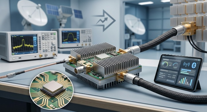
6. Can Bluetooth Integration Enhance Professional RF Power Management?
Bluetooth integration enhances professional management by enabling remote monitoring and wireless control of the amplifier’s internal parameters. By incorporating a Bluetooth-capable RF Power Amplifier, you can adjust bias levels, monitor thermal health, and switch inputs via a mobile device. This connectivity eliminates the need for physical access in remote installations or crowded laboratory racks. Modern engineering ensures that these wireless modules do not introduce interference into the high-power signal path.
H3: Wireless Control and Signal Processing
Remote interfaces allow you to fine-tune signal gain and output levels from a safe distance in high-power testing environments. This wireless capability streamlines the calibration process and provides real-time feedback on the amplifier’s operational status.
- Remote volume and gain adjustment
- Thermal status monitoring
- Input source switching
- Safety cutoff control
H3: Receiver Modules and Audio Codec Compatibility
In some professional audio or communication setups, Bluetooth acts as the primary signal input using high-fidelity codecs like aptX. These modules must be shielded to prevent the high-frequency power of the main circuit from disrupting wireless data reception.
It gets even better.
Key Takeaway: Bluetooth adds a layer of modern convenience and safety to RF systems, allowing for seamless remote interaction without compromising signal integrity.
| Integration Element | Purpose |
|---|---|
| Bluetooth Module | Wireless signal reception and decoding |
| Codec Support | Maintaining signal quality (aptX, AAC) |
| Remote Interface | Smartphone or PC control of power stages |
The ability to monitor system health wirelessly reduces the risk of equipment failure and simplifies the management of complex RF networks.
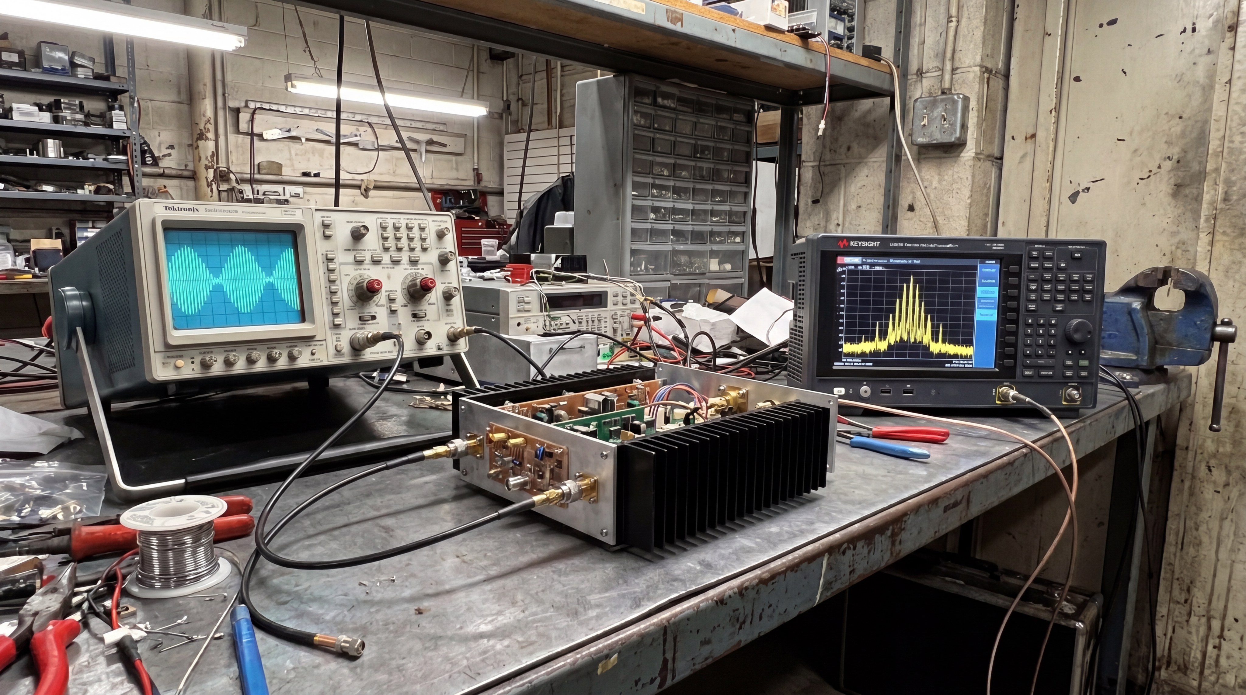
7. Why Is Linearity the Deciding Factor in Radar and Satellite Systems?
Linearity is critical because it ensures that the output signal is an exact, non-distorted replica of the input, which is vital for accurate target detection. In an RF Power Amplifier, non-linear behavior creates intermodulation products that can mask true radar returns or cause ghost images. You rely on linear performance to maintain the phase integrity of complex waveforms used in modern satellite modulation schemes. Without high linearity, the increased noise floor can lead to dropped connections or incorrect data interpretation in high-stakes environments.
H3: Minimizing Harmonic Distortion in Critical Loads
Harmonic distortion occurs when the amplifier introduces frequencies that were not present in the original signal. You must use high-linearity amplifiers to prevent these harmonics from interfering with adjacent channels and violating regulatory standards.
- Reduction of intermodulation (IMD)
- Preservation of phase information
- Lower noise floor
- Regulatory compliance
H3: Accurate Target Tracking in Complex Environments
Radar resolution depends on the amplifier’s ability to reproduce sharp pulses without distortion or “ringing.” By maintaining a linear gain response across the entire bandwidth, you ensure that small targets are not lost among background clutter.
This is the key.
Key Takeaway: In radar and SATCOM, linearity is the difference between precise data acquisition and a complete loss of signal clarity.
| Metric | Importance in Radar | Impact of Failure |
|---|---|---|
| Gain Flatness | Uniform response over bandwidth | Signal loss at specific frequencies |
| Linearity | Accurate waveform reproduction | False detections or ghost images |
| Phase Stability | Consistent signal timing | Poor target tracking |
Investing in linear amplification technology is essential for any system where the accuracy of the signal determines the success of the mission.
8. How Do Specialized Pulsed Amplifiers Handle High-Peak Power Demands?
Specialized pulsed amplifiers are engineered to deliver massive bursts of energy in millisecond intervals while maintaining thermal stability during “off” periods. An RF Power Amplifier designed for pulsed operation can reach peak power levels in the tens of kilowatts without melting its internal circuitry. You benefit from duty cycle management that allows the device to cool down between pulses, optimizing energy usage for radar and EM simulation. This capability is vital for detecting objects at extreme ranges where continuous power would be prohibitively expensive and hot.
H3: Managing Peak Power for Radar Pulse Applications
Handling tens of kilowatts requires advanced power combining techniques and robust semiconductor materials like Gallium Nitride (GaN). These designs prioritize rise and fall times to ensure that the pulse shape remains sharp for maximum target resolution.
- High-speed switching circuitry
- Energy storage capacitors
- Peak power combining
- Fast pulse modulation
H3: Pulse-Width Modulation and Thermal Stability
The thermal load of a pulsed system is a function of the duty cycle, or the ratio of “on” time to “off” time. By managing this ratio, you can push the amplifier to its physical limits during the pulse while keeping the average temperature within safe bounds.
You need to know this.
Key Takeaway: Pulsed amplifiers allow for extreme power levels that would be impossible in continuous wave mode, provided that duty cycles are strictly managed.
| Pulsed Parameter | Detail |
|---|---|
| Duty Cycle | The ratio of “on” time to “off” time |
| Peak Power | Maximum power during the pulse |
| Rise/Fall Time | Speed of signal transition |
Engineering for pulsed power requires a deep understanding of energy storage and rapid heat dissipation to prevent catastrophic device failure.
9. What Role Does Frequency Coverage Play in Selecting the Right Platform?
Frequency coverage dictates the operational range of your equipment and determines which semiconductor materials are most suitable for your RF Power Amplifier. You must match the amplifier’s bandwidth to your application, whether it is 30 MHz–6 GHz for UAVs or up to 110 GHz for millimeter-wave research. Broader frequency coverage offers versatility, but narrowband amplifiers often provide higher efficiency for specific, fixed-frequency tasks. Selecting the right platform ensures that your signal gain remains flat across the entire required spectrum.
H3: Navigating Standard 30 MHz–6 GHz Ranges
The 30 MHz to 6 GHz range covers the majority of modern tactical communications, software-defined radios, and consumer wireless protocols. You will find that standard broadband platforms in this range are designed for fast deployment and stable performance across multiple bands.
- UAV and SDR links
- Tactical radio systems
- General laboratory testing
- Cellular and Wi-Fi bands
H3: Microwave and Millimeter-Wave System Integration
Higher frequencies above 18 GHz require precision engineering and micro-assembly to handle the shorter wavelengths. You need these high-frequency platforms for next-generation satellite links and advanced radar systems that require massive data throughput.
Wait, there’s more.
Key Takeaway: Your frequency requirement is the foundational specification that determines the architecture and material science of your chosen amplifier.
| Frequency Band | Range | Common Application |
|---|---|---|
| Broadband | 30 MHz – 6 GHz | UAV, SDR, Tactical Comms |
| Microwave | 6 GHz – 40 GHz | Satellite, High-speed Data |
| mmWave | 40 GHz – 110 GHz | Research, Laboratory Test |
Matching the frequency response of the amplifier to the antenna system is necessary to prevent signal reflections and maximize power transfer.
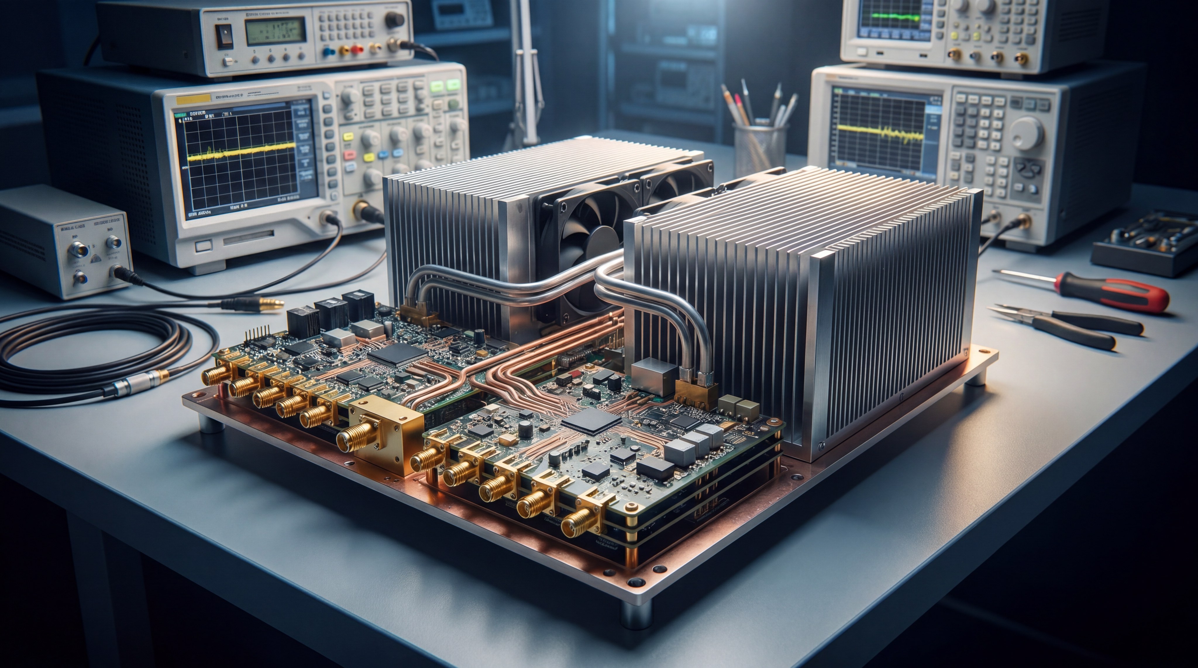
10. Why Is Thermal Management Critical for Long-Term RF Reliability?
Thermal management is critical because heat is the primary cause of semiconductor degradation and premature failure in any RF Power Amplifier. You must dissipate the heat generated by the amplification process to keep the junction temperature within safe operating limits. Without effective cooling, the gain of your amplifier will drop, and the linearity will degrade as the components experience thermal drift. Advanced materials like Gallium Nitride (GaN) offer better thermal conductivity, but they still require a robust mechanical cooling strategy to survive continuous operation.
H3: Heat Dissipation in High-Gain Circuits
High-gain circuits concentrate significant energy in a small physical area, necessitating the use of CNC-machined heat sinks and thermal spreaders. You can choose between conduction cooling, forced air, or liquid cooling depending on the total power output of your system.
- Forced air (Fan-based)
- Conduction (Heat sinks)
- Liquid cooling (High-power racks)
- Phase-change cooling
H3: Materials and Cooling for Continuous-Wave Operation
Continuous-wave (CW) operation is thermally demanding because there is no “off” period for the components to cool down. You must ensure that your enclosure and mounting strategy provide a low-resistance path for heat to travel away from the active chips.
Consider this carefully.
Key Takeaway: Robust thermal design is the insurance policy for your RF investment, ensuring that your hardware performs consistently for years.
| Cooling Method | Effectiveness | Application Size |
|---|---|---|
| Air (Fan) | Moderate | Standard Modules |
| Conduction | High | Integrated Subsystems |
| Liquid Cooling | Very High | Multi-kW Rack Systems |
Reliability is built through thermal engineering, as a cool-running amplifier is always a long-lasting amplifier.
FAQ
- Can I customize a power amplifier for non-standard frequency bands?
Yes. Most factory-direct manufacturers offer project-based engineering to adapt standard platforms to your specific frequency and power requirements. - How do I protect my amplifier from high VSWR during operation?
Ensure you are using units with built-in VSWR protection circuitry, which automatically limits power if reflections from the load are too high. - Can I use a pulsed amplifier for continuous wave (CW) applications?
Generally no. Pulsed amplifiers are optimized for high peak power but lack the thermal dissipation required for the constant load of CW signals. - How do I decide between Class AB and Class D for my project?
Choose Class AB if you need maximum signal purity for communication; select Class D if your priority is compact size and battery efficiency. - Can I monitor my RF system status remotely without physical cables?
Yes. Integration of Bluetooth or digital control interfaces allows you to monitor thermal health and bias levels via wireless modules.
Conclusion
Selecting the right power amplifier requires a deep understanding of classes, frequency coverage, and thermal demands. Whether you are building a satellite uplink or a laboratory testing environment, the quality of your amplification defines the success of your signal. By addressing the challenges of signal loss and thermal instability with high-performance solid-state solutions, you ensure your mission-critical infrastructure remains resilient and precise. CorelixRF is dedicated to providing factory-direct RF excellence, helping engineering buyers move from requirement review to validated delivery. For high-performance, factory-direct RF solutions that meet your most demanding project specs, contact us today to discuss your specific requirements.