Power amplifiers categorize into classes such as A, AB, and D, and are defined by parameters like gain, linearity, and efficiency to match specific transmission needs. Selecting an inadequate RF Power Amplifier often leads to catastrophic system failures or unrecoverable signal distortion in high-stakes environments. A mismatched unit doesn’t just degrade performance; it threatens mission-critical UAV links and satellite communications while driving massive budget overruns. This comprehensive guide breaks down the essential types and technical parameters you need to optimize your signal chain successfully.
What is a basic RF Power Amplifier definition?
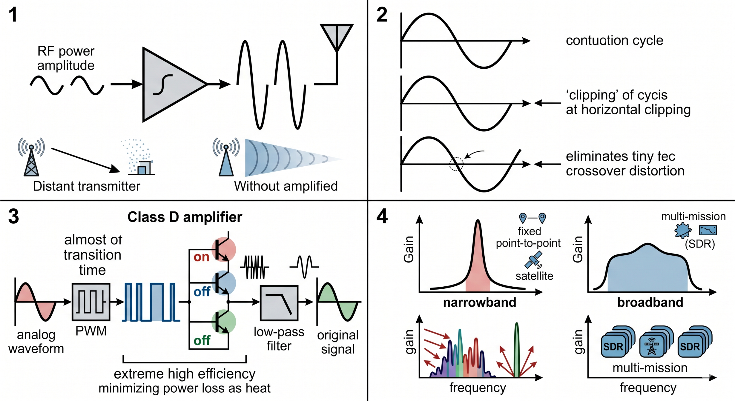
The basic definition of an RF Power Amplifier is a circuit that converts low-power radio frequency signals into a much higher power level to drive an antenna. You utilize these devices to ensure that a signal has sufficient amplitude to overcome path loss during long-distance transmission. Without this amplification, your signal would simply dissipate before reaching its destination.
What role does it play in the signal chain?
It serves as the final active stage before the antenna in a transmitter architecture. You rely on it to provide the necessary current and voltage swing to match the impedance of the transmission line. This stage is critical for maintaining the Signal-to-Noise Ratio (SNR) across the link.
Why is thermal management a priority?
Thermal management is vital because power conversion is never 100% efficient, and excess energy turns into heat. You must ensure proper heat sinking to prevent the semiconductor junctions from reaching their thermal breakdown point. Excessive heat can also cause gain drift, which alters your output parameters during operation.
But that’s not all.
How do Class A, B, and AB RF amplifiers differ?
Class A, B, and AB amplifiers differ primarily in their conduction angle and the resulting trade-off between signal linearity and power efficiency. Every RF Power Amplifier in these categories handles the input waveform differently to meet specific project requirements. You must choose based on whether your application prioritizes spectral purity or battery life.
Is Class A the best for high-linearity tasks?
Class A is the most linear choice because the output transistor conducts for the full 360 degrees of the signal cycle. You get the lowest possible distortion, making it ideal for laboratory testing and precision instrumentation. However, the efficiency is very low, often staying below 25% because the device is always “on.”
Why is Class AB the industry standard?
Class AB is the industry standard because it balances the high efficiency of Class B with the low distortion of Class A. In this configuration, the transistors conduct for slightly more than 180 degrees to eliminate crossover distortion. You will find this topology in most broadband communication systems today.
Think about it.
Key Takeaways:
- Class A provides maximum linearity but generates the most heat.
- Class B is efficient but suffers from signal “clipping” at the zero-crossing.
- Class AB offers a reliable middle ground for commercial B2B hardware.
| Amplifier Class | Conduction Angle | Efficiency | Primary Benefit |
|---|---|---|---|
| Class A | 360° | 20-30% | Purest Linearity |
| Class B | 180° | 60-70% | High Efficiency |
| Class AB | 180° – 200° | 50-60% | Balanced Performance |
Refer to this class comparison to determine which conduction angle fits your specific linearity requirements.
Why is the Class D RF Power Amplifier so efficient?
The Class D RF Power Amplifier achieves extreme efficiency by operating the output transistors as fast-acting switches rather than linear resistors. By using a product platform built on switching technology, you minimize the time the transistor spends in the high-dissipation region. This allows you to achieve efficiencies exceeding 90% in many industrial applications.
How does switching technology work?
The input signal is modulated into a series of pulses through Pulse Width Modulation (PWM). These pulses drive the transistors to either a fully “on” or fully “off” state. Because the transistors are rarely in the intermediate state, power loss as heat is significantly reduced.
What are the challenges with Class D noise?
Switching noise is the primary challenge because the high-speed transitions generate unwanted harmonics. You must implement robust low-pass filtering at the output to recover the original analog waveform. Failure to filter properly can lead to interference with nearby sensitive electronics.
Here is the deal.
Key Takeaways:
- Class D units are often referred to as “digital amplifiers” due to their binary states.
- They are ideal for portable, battery-powered systems where heat dissipation is limited.
- Output filtering is non-negotiable to maintain spectral compliance.
| Feature | Class D Detail |
|---|---|
| Efficiency | Typically 85% to 95% |
| Form Factor | Compact and lightweight |
| Filtering | High-order Low Pass Filter required |
Evaluate the trade-off between high-frequency switching noise and power savings for your mobile deployments.
Should you choose single-ended or push-pull designs?
You should choose a push-pull design if you require high power and low harmonic distortion, whereas single-ended designs are for simpler, low-cost tasks. A high-quality RF Power Amplifier often uses the push-pull topology to cancel out even-order harmonics. This structural choice directly impacts the “cleanness” of your transmitted spectrum.
When is single-ended architecture used?
Single-ended designs use one active element to process the entire signal, making them very cost-effective. You will find these in low-power modules where complexity needs to be minimized. However, they are prone to higher levels of second-harmonic distortion.
Does push-pull improve output power?
Push-pull significantly improves output power by splitting the signal into two phases that are handled by separate transistors. By recombining them at the output, you double the potential power delivery while canceling out noise. This makes it the preferred architecture for high-wattage base station transmitters.
The best part?
Key Takeaways:
- Single-ended is cheaper but limited by thermal strain on one device.
- Push-pull cancels even harmonics (2nd, 4th, etc.) through phase symmetry.
- Wideband performance is generally superior in push-pull configurations.
| Design Type | Component Count | Noise Rejection | Power Ceiling |
|---|---|---|---|
| Single-Ended | Low (1 Transistor) | Low | Low to Moderate |
| Push-Pull | High (2 Transistors) | High (Even Harmonics) | High |
Analyze the harmonic requirements of your local regulations before committing to a single-transistor architecture.
How do solid-state and tube amplifiers compare?
Solid-state amplifiers offer superior reliability and smaller size, while tube amplifiers are reserved for extreme high-power millimeter-wave needs. Modern standard platforms utilize Gallium Nitride (GaN) to bridge the gap between these two technologies. You will likely prefer solid-state for any application requiring instant-on capability and long-term durability.
Why is solid-state (SSPA) the dominant choice?
SSPAs are dominant because they lack the fragile filaments and high-voltage requirements of vacuum tubes. You benefit from a much higher Mean Time Between Failures (MTBF), which reduces your maintenance costs. Additionally, they can be integrated into small enclosures for UAV or vehicle mounting.
Are vacuum tubes (TWTAs) still relevant?
TWTAs remain relevant for satellite ground stations requiring tens of kilowatts at microwave frequencies. You might still use them when solid-state combining becomes too complex or inefficient at millimeter-wave bands. However, they require significant warm-up time and periodic replacement.
But wait, there’s more.
Key Takeaways:
- GaN technology has allowed solid-state units to reach 10kW+ power levels.
- SSPAs operate at lower, safer voltages than traditional tube units.
- TWTAs are the “heavy lifters” for specific high-frequency satellite links.
| Attribute | SSPA (Solid-State) | TWTA (Tube) |
|---|---|---|
| Reliability | Excellent | Limited (Wear-out) |
| Startup | Instant | 3-5 Minute Warm-up |
| Size | Compact | Large / Heavy |
Review your mission duration and maintenance access before selecting between these two core technologies.
What defines a high-frequency RF Power Amplifier?
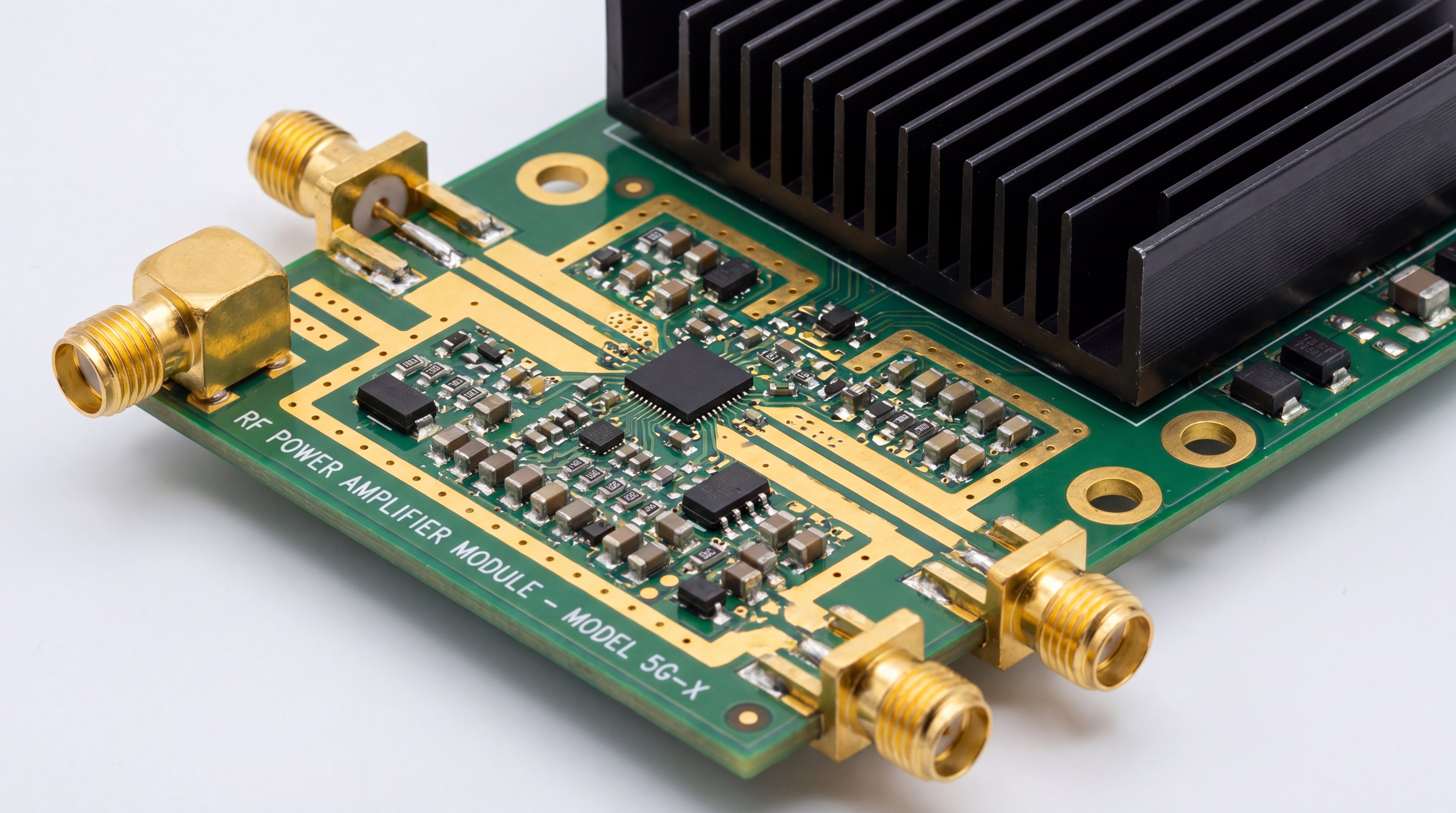
A high-frequency RF Power Amplifier is defined by its ability to maintain gain and stability at frequencies reaching up to 170 GHz. As you move into the microwave and millimeter-wave regions, the physical layout of the circuit becomes as important as the components themselves. You must account for parasitic capacitance and inductance that don’t exist at lower bands.
How does wavelength impact circuit design?
At high frequencies, the wavelength is so short that every millimeter of trace behaves like an antenna or inductor. You need precision-machined enclosures and high-frequency laminates like Rogers to prevent signal leakage. Without these materials, your gain would drop off sharply before reaching the output port.
What is the role of MMIC technology?
Monolithic Microwave Integrated Circuits (MMIC) allow for the integration of multiple stages on a single die. You utilize MMICs to minimize the distance signals travel between transistors, which is critical for microwave stability. This technology is the backbone of modern 5G and satellite communication front-ends.
It gets better.
Key Takeaways:
- High-frequency units require VSWR protection to prevent damage from reflections.
- Shielding must be seamless to avoid electromagnetic interference (EMI).
- Connector selection (SMA vs. 2.92mm) is vital for frequency transparency.
| Frequency Band | Designation | Key Challenge |
|---|---|---|
| 1 – 6 GHz | S/C Band | General broadband matching |
| 18 – 40 GHz | K/Ka Band | Parasitic management |
| 75 – 110 GHz | W-Band | Chip-level micro-assembly |
Investigate the die-level specifications if your project requires operation above the 40 GHz threshold.
When are narrowband RF Power Amplifier units necessary?
Narrowband units are necessary when you need the absolute maximum gain and efficiency for a fixed, specific frequency band. By choosing a narrowband amplifier, you benefit from impedance matching that is optimized for a single window. You will find that these units outperform broadband models because they don’t have to compromise performance across a wide spectrum.
Do they offer better out-of-band rejection?
They naturally offer better rejection because the internal matching networks behave as filters for other frequencies. You can use this to your advantage to simplify the filtering requirements elsewhere in your system. This is especially helpful in crowded spectrums where interference is a constant threat.
Why use them for fixed satellite links?
Fixed links operate on set frequencies, so the versatility of a broadband unit is wasted energy. You can achieve higher power output with less heat by focusing all component energy into that specific channel. This translates to lower power bills and longer hardware life for remote installations.
Look at it this way.
Key Takeaways:
- Narrowband units provide the highest possible “Peak Performance.”
- They act as a hardware-level security layer against out-of-band signals.
- Tuning is fixed, so verify your operational frequency before purchase.
| Application | Best Amplifier Choice |
|---|---|
| Multi-Mission SDR | Broadband |
| Point-to-Point Link | Narrowband |
| Radar Test Bench | Broadband (Pulsed) |
Confirm your frequency plan is stable before investing in highly tuned narrowband hardware.
Which parameters define RF Power Amplifier performance?
The parameters that define performance include Gain, 1dB Compression (P1dB), Saturated Power (Psat), and efficiency. Every RF Power Amplifier is limited by its “linear range,” which tells you how much input power you can apply before the signal distorts. You must carefully audit these metrics to ensure your modulation remains intact during transmission.
What is the 1dB Compression Point?
The P1dB point is the level where the amplifier’s gain drops by 1dB from its linear value. You should avoid operating beyond this point if you are using complex digital modulations like QAM. Crossing P1dB results in signal clipping and a high bit-error rate.
How do SNR and THD affect signal quality?
Signal-to-Noise Ratio (SNR) and Total Harmonic Distortion (THD) determine the fidelity of the transmitted data. You want high SNR to ensure the signal is clearly distinguishable from background noise at the receiver. Low THD ensures you aren’t leaking power into adjacent channels, which could violate local laws.
It only gets more technical from here.
Key Takeaways:
- Always check the Psat rating to find the absolute maximum power ceiling.
- Gain flatness ensures consistent performance across your entire bandwidth.
- VSWR tolerance indicates how well the unit handles mismatched antennas.
| Parameter | Why It Matters |
|---|---|
| Gain (dB) | Determines the amplification factor |
| P1dB (dBm) | Marks the limit of linear operation |
| Efficiency (%) | Measures power wasted as heat |
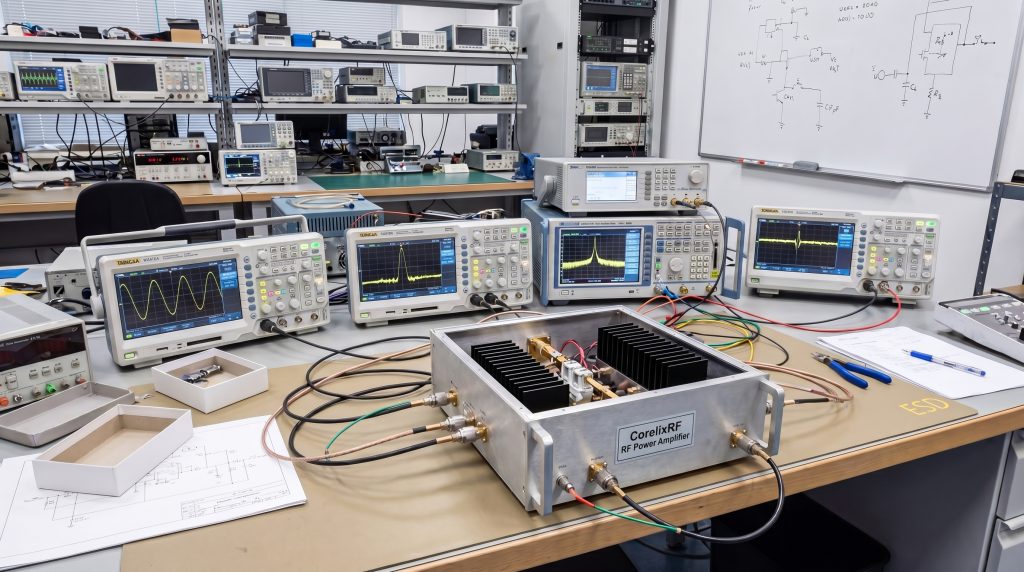
Utilize a full spectrum analyzer to verify these parameters under real-world load conditions.
Why consider a custom RF Power Amplifier solution?
You should consider a custom solution when off-the-shelf modules cannot meet your unique mechanical constraints or specialized frequency needs. A custom-engineered RF Power Amplifier allows you to integrate specific control interfaces or liquid cooling systems directly into the chassis. This approach eliminates the need for bulky adapters and secondary cooling units.
Can custom designs optimize system weight?
Custom designs allow for the use of lightweight materials and integrated structures specifically for aerospace or UAV use. You can combine multiple functions, like filtering and switching, into a single module to save precious grams. For many B2B projects, weight reduction is the primary driver for custom development.
What about specialized interface controls?
You may need custom RS485, Ethernet, or TTL controls to match your existing software architecture. Standard units often come with generic interfaces that require complex translation layers. A custom build ensures that your control plane “talks” directly to the amplifier without latency.
Here is the bottom line.
Key Takeaways:
- Custom builds allow for non-standard frequency bands (e.g., V-band).
- They can be ruggedized for extreme environments like maritime or desert use.
- Integration costs are often lower long-term due to “perfect fit” engineering.
| Customization Option | Project Benefit |
|---|---|
| Liquid Cooling | High-density rack integration |
| Specialized Enclosure | Fits into specific UAV bays |
| Dual-Mode (CW/Pulse) | Versatile test laboratory use |
Request a feasibility review to see if a custom module can consolidate your current RF front-end.
How to select the right RF Power Amplifier for your project?
Selecting the right RF Power Amplifier requires a deep audit of your frequency range, required output power, and thermal environment. You must also consider the duty cycle—whether the unit will run continuously (CW) or in short bursts (Pulsed). The truth is, the most expensive module is often the one that fails because it wasn’t matched to the load correctly.
Why is the duty cycle critical?
The duty cycle determines the average power dissipated by the device, which affects your cooling requirements. You cannot run a pulsed-rated amplifier at 100% duty without risking an immediate thermal shutdown. Conversely, buying a CW unit for a 1% duty cycle application is an unnecessary expense.
Should you demand factory test data?
You should always demand unit-level test data to verify that the hardware meets the datasheet specifications. Sample data is not enough for mission-critical systems; you need to know exactly how your unit performs. This data serves as your baseline for system-level integration and troubleshooting.
The truth is.
Key Takeaways:
- Start with the “Big Three”: Frequency, Power, and Efficiency.
- Verify the cooling path—will you have forced air or a cold plate?
- Work with a manufacturer that provides direct engineering support.
| Selection Step | Critical Question |
|---|---|
| 1. Bandwidth | Is it broadband or narrowband? |
| 2. Power Level | What is the required P1dB for my modulation? |
| 3. Interface | How will my system monitor the temperature/VSWR? |
Prepare a detailed technical requirement document (TRD) before starting your procurement process.
Technical FAQ
Can I use an audio amplifier for RF applications?
No. Audio amplifiers are designed for low frequencies (20Hz-20kHz) and high-impedance loads, whereas RF units operate in MHz/GHz ranges and are matched to 50 ohms.
What’s the best way to prevent amplifier burnout?
Always ensure a matched load (antenna or dummy load) is connected before powering on. High VSWR reflections are the leading cause of transistor failure.
Can I run two RF Power Amplifiers in parallel?
Yes, but you must use a specialized power combiner to ensure the phases are correctly aligned. Improper combining can lead to power cancellation and thermal damage.
What is the difference between CW and Pulsed power?
CW (Continuous Wave) is 100% duty cycle, while Pulsed power is for intermittent signals like Radar. Pulsed units can often achieve much higher peak power than CW units.
How does GaN compare to LDMOS technology?
GaN (Gallium Nitride) offers higher power density and can operate at much higher frequencies than LDMOS. It is currently the preferred material for high-frequency microwave systems.
Strategic Conclusion
By understanding the various classes and parameters of modern power platforms, you can solve the critical challenges of signal distortion and thermal instability. Whether your project requires a broadband Class AB module or a high-efficiency Class D switching system, matching the hardware to your operational environment is the key to reliability. At CorelixRF, our vision is to provide factory-direct, engineering-backed solutions that push the boundaries of microwave and millimeter-wave performance. For tailored guidance on your next project, please contact us to speak with a senior RF engineer today.