
A VHF/UHF broadband RF amplifier is often selected when a project needs 30-512 MHz coverage without switching between many narrowband stages. That can be useful for communication system testing, RF laboratory evaluation, OEM transmit chains, antenna evaluation, and industrial or vehicle-side RF subsystems. But the buying decision should not stop at frequency range and output power.
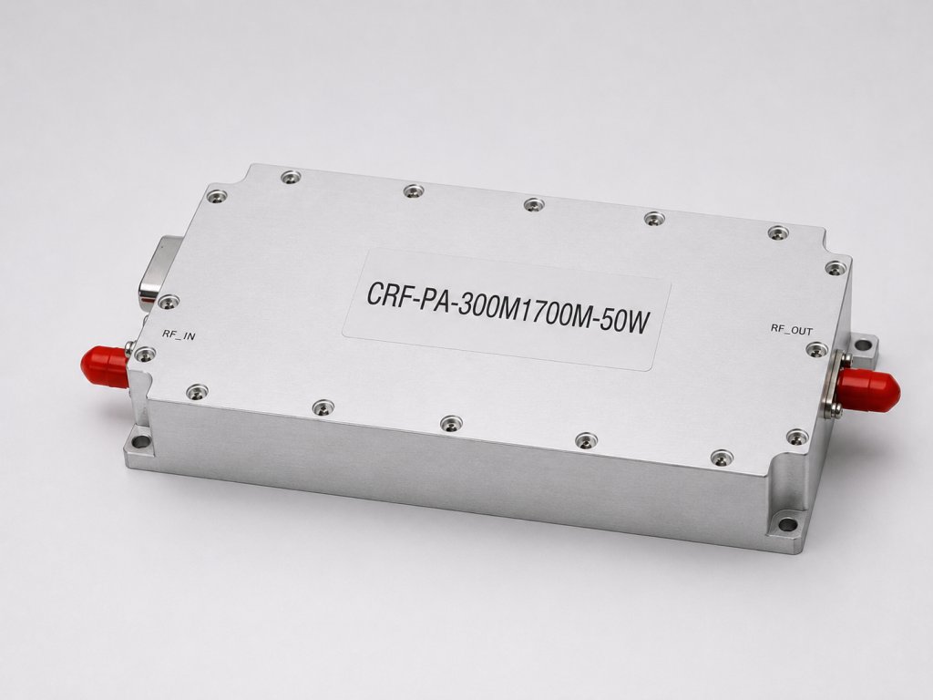
CorelixRF’s 30-512 MHz RF power amplifier platform includes standard 30 W, 50 W, 100 W, 150 W, and 200 W CW models. The page lists 28 VDC architecture, air cooling, SMA-F/N-F connector references, typical gain values from about 45 dB to 53 dB across the standard power classes, and model-level current requirements. Those details are useful because lower-band RF systems often fail at the integration stage, not during the first quotation.
Define CW Operation and Duty Conditions
The first selection issue is operating mode. A CW-rated VHF/UHF amplifier is reviewed differently from a pulsed amplifier. The same wattage can mean very different thermal and electrical stress depending on duty cycle. If a buyer asks only for “100 W,” the supplier may not know whether the requirement is continuous, intermittent, sweep-based, or part of a waveform test.
For CorelixRF’s 30-512 MHz standard series, the model table identifies output classes as CW. Engineers should still submit the real duty condition, expected operating time, ambient temperature, and cooling environment. This makes the review more useful and reduces the risk of selecting a model that works on paper but not inside the final enclosure.
Match Power Class to Current Budget
The 30-512 MHz page provides different current values by output class: for example, lower current for 30 W and higher current for 200 W. This is critical for 28 VDC system planning. The amplifier is only one part of the power architecture. Cable gauge, PSU headroom, connectors, inrush behavior, and thermal margin should be planned before the mechanical design is frozen.
If a platform already uses a 28 VDC rail, the native architecture can simplify integration. If it does not, the system may need a DC conversion stage, and that stage must be sized for real current demand. Procurement teams should request maximum current information by model rather than relying on a generic power estimate.
Review Gain and Input Drive
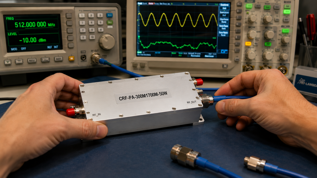
The CorelixRF page lists typical gain ranges such as 45 dB to 53 dB depending on power class. Gain affects how much source drive is required. A signal generator, SDR source, exciter, or upstream RF module must provide a suitable input level without overdriving the amplifier.
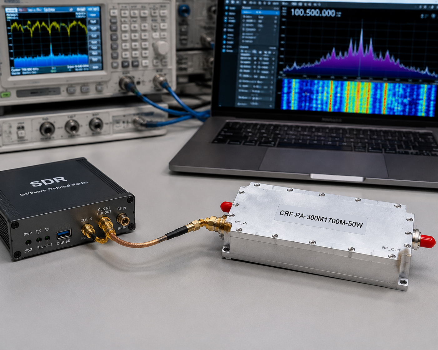
For SDR-driven lower-band work, the SDR + amplifier integration path can be useful because it reviews source output, amplifier input, frequency overlap, connector path, and output-side condition together. This is especially important when the SDR source does not cover the full 30 MHz lower edge, and the effective matched range begins at the overlap between the SDR and amplifier.
Air Cooling and Mechanical Fit
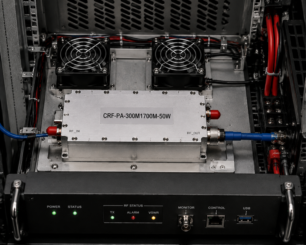
CorelixRF describes the 30-512 MHz standard series as air cooled. Air cooling is practical, but it requires sufficient airflow over the module housing and a mechanical layout that does not block the heat path. Continuous-duty or high-power use should include enclosure airflow, mounting orientation, nearby heat sources, and service access in the review.
Mechanical drawings should be requested early for OEM integration. The 30 W and 50 W classes can use a compact footprint, while higher power models may use larger dimensions. Cable routing and connector clearance can become difficult if the amplifier is selected after the enclosure is already designed.
When to Consider a Custom Sub-Band
Full 30-512 MHz coverage is valuable when the application needs wide VHF/UHF agility. But many projects operate in a narrower portion of the band. CorelixRF notes that sub-band optimization can be reviewed where full wideband coverage is not the best fit. A custom sub-band may help with gain flatness, efficiency, thermal behavior, or mechanical requirements.
If the project moves above 300 MHz and into L-band, the 300-1700 MHz RF amplifier platform may be a better fit. If the project requires 30 MHz lower-band coverage, the 30-512 MHz platform is the relevant starting point.
Documentation and Validation
Technical buyers often need more than a datasheet. They may need test records, output power behavior, gain response, VSWR information, mechanical drawings, and shipment documentation. CorelixRF describes unit-level RF validation and documentation packages as available based on model scope and project stage. The RFQ should state which documents are required for internal review.
FAQ
What is a VHF/UHF broadband RF amplifier used for?
It is used for RF testing, communication validation, antenna evaluation, OEM subsystem integration, and broadband transmit-chain development across lower RF bands.
Why is current budget important for a 28 VDC amplifier?
Higher power classes can require much more current. The power supply, cabling, connectors, and thermal path must be sized for the selected model.
Should I choose full 30-512 MHz coverage or a custom band?
Choose full coverage for frequency-agile systems. Ask for custom sub-band review when the real operating range is narrower and performance or integration tradeoffs matter.
What should be confirmed before quotation?
Confirm CW or pulse operation, frequency range, output power, gain, input drive, cooling, supply voltage, current, connector type, dimensions, and documentation needs.