
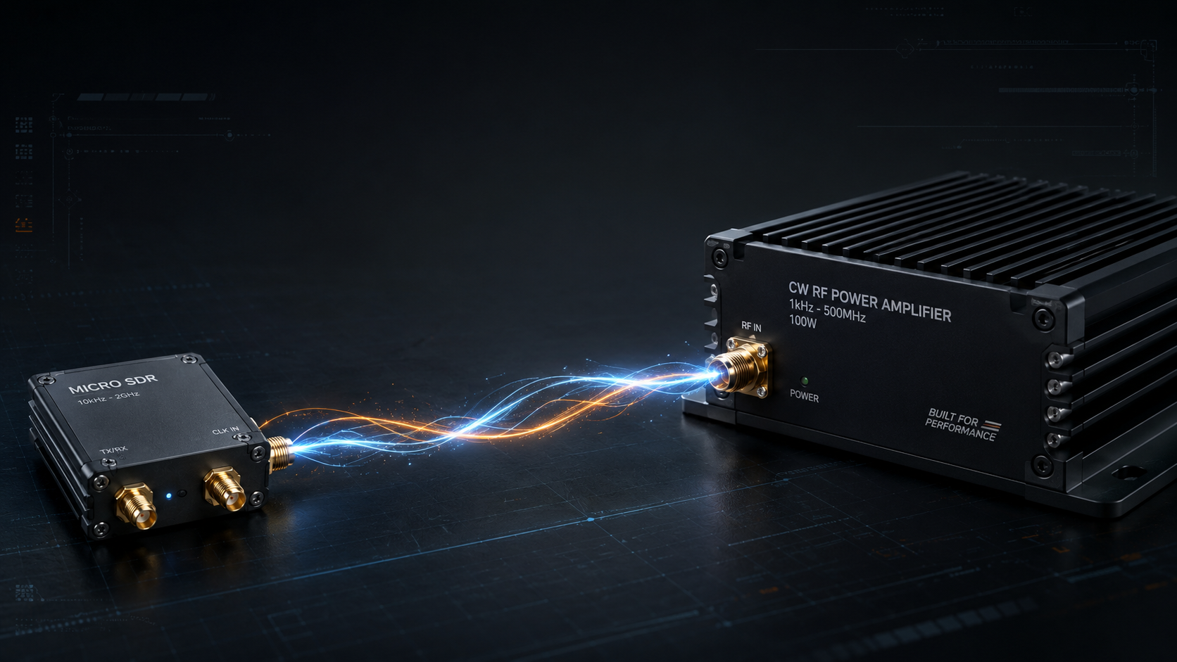
Many SDR projects reach a point where the source can generate the right waveform but cannot deliver the required RF power at the antenna, DUT, chamber input, or system port. That is when SDR RF amplifier integration becomes a practical engineering problem. The challenge is not only choosing an amplifier with a similar frequency range. The SDR output level, amplifier input drive, connector path, control interface, power supply, load condition, and validation method all need to work together.
CorelixRF describes its SDR + CW RF power amplifier system as a matched path between a 100 MHz-6 GHz SDR source module and CW amplifier platforms including 30-512 MHz, 300-1700 MHz, 300-2700 MHz, and 2-6 GHz. The page is clear that pulsed amplifier projects require a separate engineering path. That distinction is important because CW output, pulsed output, duty cycle, and timing behavior are not interchangeable.
Frequency Overlap Comes First
An SDR source may cover 100 MHz-6 GHz, but the final operating range of the amplified system is limited by the selected amplifier platform. If the project uses lower VHF/UHF frequencies, the 30-512 MHz RF power amplifier platform may be relevant, but the amplified SDR range begins only where the SDR and amplifier overlap. For mid-band UHF to L-band projects, the 300-1700 MHz RF amplifier path may be more direct. For wider UHF to S-band needs, the 300-2700 MHz GaN RF amplifier range should be reviewed. For S/C-band systems, the 2-6 GHz RF amplifier platform is usually the cleaner starting point.
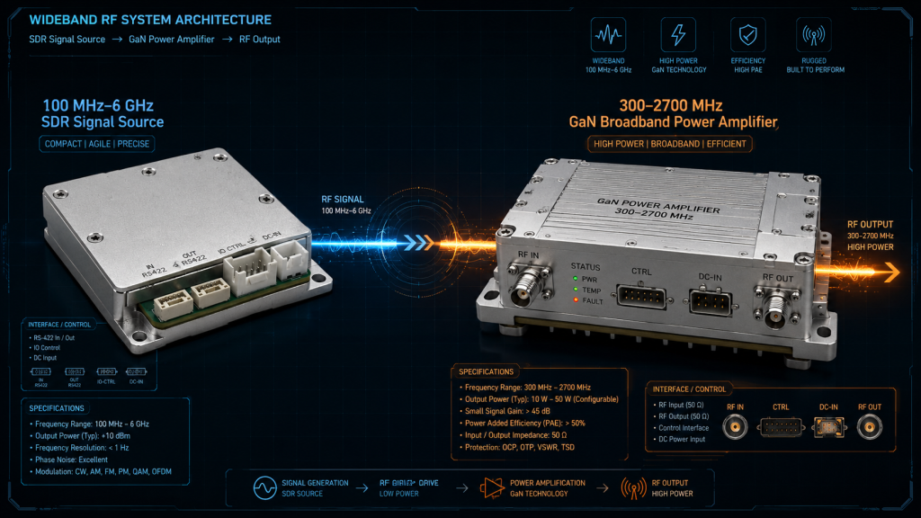
The RFQ should define the actual working band, not simply request “100 MHz to 6 GHz amplification.” A single broadband chain may not be the best technical or commercial answer if the real requirement is concentrated in one or two sub-bands.
SDR Output Level Must Match Amplifier Input
The most common integration failure is drive mismatch. An SDR module has a defined RF output level. A power amplifier has an input drive range or sensitivity requirement. If the source level is too low, the amplifier may not reach the desired output. If it is too high, the system may require attenuation, limiting, or a protection strategy to avoid overdrive.
This is why the SDR and amplifier should be reviewed as a chain. The request should include waveform type, expected output level, modulation condition, frequency range, and whether the amplifier will operate near rated power or with deliberate back-off. Engineers should also define whether the system needs linear behavior for modulation testing or saturated output for a simpler CW power application.
Connector and Cable Path Affect Real Output
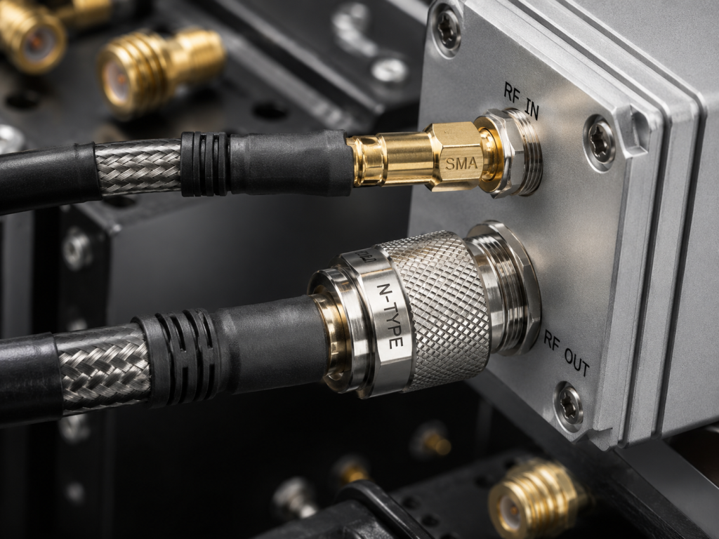
The RF path between SDR and amplifier is not lossless. SMA connectors, N-type outputs, coax length, adapters, attenuators, couplers, and switches can change drive level and output power. CorelixRF’s SDR integration page lists SMA output for the SDR source, RS422 control, 9-32 VDC power supply, and a compact 60 x 140 x 14 mm module format. It also references amplifier platform connector paths such as SMA and N-type across CW amplifier models.
For reliable SDR RF amplifier integration, engineers should provide the intended connector plan and cable path. A mismatch on the connector side can slow a project as much as an electrical mismatch, especially when the system is moving from a bench setup into an OEM enclosure.
Choose the Right CW Amplifier Power Class
CorelixRF’s SDR matching page groups CW amplifier paths into 30-512 MHz, 300-1700 MHz, 300-2700 MHz, and 2-6 GHz platforms with 30 W to 200 W classes in those standard paths. The correct power class depends on delivered power at the output condition, not only on the amplifier label. For antenna output, include antenna power handling and VSWR risk. For DUT input, include attenuation, protection, and measurement limits. For chamber or EMC-style environments, define whether the amplifier is used for repeatable field generation or component-level exposure.
Control Interface and Power Supply Planning
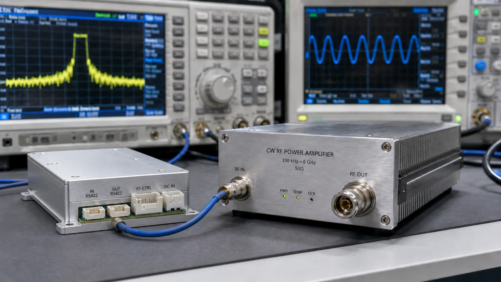
SDR systems are often controlled by host software, while amplifier platforms may use separate control logic, enable signals, alarms, or remote interfaces. CorelixRF lists RS422 for its SDR module and notes that connector/control customization may be reviewed for projects. A serious integration request should describe whether the customer wants independent operation, coordinated software control, rack integration, or embedded OEM control.
Power supply planning should be handled the same way. The SDR module uses a 9-32 VDC supply according to the CorelixRF page, while many CW amplifier paths use 28 VDC architecture. Higher frequency or higher power platforms may have different supply requirements. Mixing power domains without planning can create grounding, noise, and safety problems.
Output-Side Conditions Decide the Final Review
The amplifier output may feed an antenna, load, attenuator, chamber input, DUT, or customer RF port. Each condition changes the review. Antenna paths require power handling, impedance, cable loss, and VSWR awareness. DUT paths may require attenuation and measurement protection. Embedded systems need mechanical, cooling, grounding, and serviceability review.
The better request is not “quote an SDR amplifier.” It is “review this SDR source, this frequency range, this CW output target, this load condition, and this integration format.” That gives the engineering team enough context to recommend a standard platform or a custom path.
FAQ
Can one SDR amplifier chain cover 100 MHz to 6 GHz?
The SDR source may cover 100 MHz-6 GHz, but the amplified system range depends on the selected CW amplifier platform and the actual overlap between the source and amplifier.
Is pulsed operation included in SDR + CW amplifier matching?
No. The CorelixRF SDR matching path is explicitly based on CW amplifier platforms. Pulsed RF projects require separate review because pulse width, duty cycle, and timing behavior change the amplifier selection.
Why does SDR output level matter?
The SDR must provide an output level suitable for the amplifier input. Too little drive may not reach output power; too much drive may require attenuation or protection.
What should I send for an SDR RF amplifier RFQ?
Send frequency range, waveform type, SDR output level, required CW output power, connector preference, control interface, load condition, power supply limits, and project stage.