
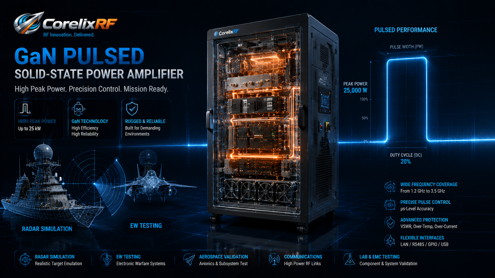
A pulsed RF power amplifier should be specified from the pulse profile first. Frequency and peak power matter, but pulse width, duty cycle, gain, cooling, connector choice, control interface, and protection behavior often decide whether the amplifier is suitable for radar simulation, EW testing, communications validation, or aerospace RF development.
CorelixRF’s local pulsed amplifier specifications include examples such as 0.4-1 GHz 1500 W, 1-2 GHz 1500 W, 1.2-1.4 GHz 500 W, 2.7-3.1 GHz 500 W, and 2.9-3.5 GHz 25 kW platforms. The files show GaN pulsed SSPA configurations with pulse-width and duty-cycle examples, gain control, rack or cabinet formats, temperature/current diagnostics, alarm protection, and project-ready control interfaces. This makes pulsed RF a strong topic for a custom RF amplifier RFQ discussion.
Start with pulse width and duty cycle
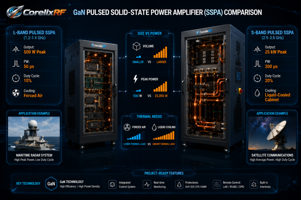
For pulsed amplifiers, peak output power can be misleading if the duty cycle is not defined. One CorelixRF reference lists 1-2 GHz, 1500 W output, 1-50 us typical pulse width, and 5% duty cycle. Another lists 1.2-1.4 GHz, 500 W output, 50 us typical pulse width, and 10% duty cycle. A higher-power 2.9-3.5 GHz reference lists 25 kW peak output, 200 us typical pulse width, and 20% duty cycle.
Those examples show why an RFQ must include pulse width, pulse repetition behavior, duty cycle, burst duration, and cooling environment. A pulsed RF power amplifier cannot be correctly reviewed from peak watts alone.
Define frequency coverage and peak power together
A radar simulation amplifier may need a narrow L-band or S-band window. An EW lab system may need broader coverage. CorelixRF’s pulsed examples include 0.4-1 GHz, 1-2 GHz, 1.2-1.4 GHz, 2.7-3.1 GHz, and 2.9-3.5 GHz configurations, so buyers should state whether they need a fixed band, a tunable setup, or a wider platform.
Peak power should be stated at the required output port after known system losses. If the output feeds a switch matrix, coupler, antenna, load, or chamber path, include those losses in the requirement. For system-level RF testing and validation, define calibration points and safe output limits before automation begins.
Review gain control, interfaces, and alarm behavior
The pulsed datasheets show gain control examples and monitoring features such as temperature/current diagnostics and alarm protection. In a pulsed system, alarm behavior should be part of the test logic. If the amplifier reports a fault, should the controller remove RF drive, stop the pulse generator, trigger a shutdown, or log the event and continue at reduced settings?
For integrated systems, ask for control protocol details, I/O behavior, timing requirements, interlock support, and documentation that can be used by the software and safety teams.
Cooling format follows average power
A pulsed amplifier with high peak power may still be manageable if duty cycle is low, while a high-duty profile can require serious thermal planning. CorelixRF examples include rack-mount and water-cooled cabinet platforms. The mechanical choice should follow average power, airflow or water-cooling availability, service access, and installation constraints.
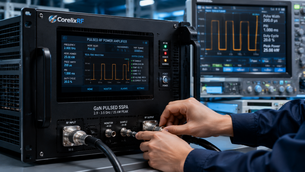
Teams should provide ambient temperature, rack space, coolant details if applicable, duty cycle, burst duration, and expected operating schedule. CorelixRF’s manufacturing and engineering support can help align final drawings, test data, and control documentation with the selected configuration.
RFQ checklist for pulsed amplifier projects
Prepare these details before requesting review:
- Frequency range and required bandwidth.
- Peak output power at the amplifier output or final load.
- Pulse width, PRI/PRF, duty cycle, and burst duration.
- Waveform type and modulation details.
- Input drive level and required gain margin.
- RF connector or waveguide preference.
- Rack, module, or cabinet limits.
- Cooling method and ambient conditions.
- Control interface, alarms, and interlock requirements.
- Required test data, drawings, and documentation.
This information helps CorelixRF recommend an existing RF power amplifier platform or define a tailored pulsed amplifier configuration.
How to avoid underspecified pulsed amplifier quotes
Many pulsed amplifier RFQs arrive with only frequency and peak power. That is not enough. The supplier also needs pulse width, PRF or PRI, duty cycle, burst length, waveform, input drive level, expected gain control range, output connector, cooling method, and the intended control interface. Without those details, two quoted amplifiers may look comparable while being designed for very different operating stress.
The local CorelixRF pulsed specifications show why this matters. A 1-2 GHz 1500 W platform with 1-50 us typical pulse width and 5% duty cycle is a different thermal and control problem from a 2.9-3.5 GHz 25 kW cabinet platform with 200 us typical pulse width and 20% duty cycle. Both are pulsed RF amplifiers, but the installation, cooling, output interface, and safety review are not the same.
Content angle for procurement and engineering readers
This article should speak to both engineers and technical buyers. Engineers need the pulse-profile checklist, while procurement teams need to understand why a lower headline price may not be comparable if the duty cycle, cooling format, or documentation package differs. The strongest SEO angle is therefore not simply pulsed RF amplifier for sale; it is pulsed RF power amplifier RFQ guide for radar simulation and EW testing.
That keyword reflects the real search intent: the reader is likely preparing a requirement and wants to avoid missing information. The CTA should send them to CorelixRF’s contact page with enough context to request an engineering review rather than a generic catalog response.
FAQ
What is the most important pulsed RF amplifier specification?
Pulse width, duty cycle, and peak output power must be evaluated together. Peak power alone is not enough to determine suitability.
What applications use pulsed RF power amplifiers?
Common uses include radar simulation, EW testing, communications validation, aerospace RF systems, and high-power pulsed test instrumentation.
Why does cooling matter if the amplifier is pulsed?
Average power and duty cycle still create heat. High peak power with a high duty cycle may require rack-level airflow planning or liquid cooling.
What should I send CorelixRF for a pulsed amplifier review?
Send frequency, peak power, pulse width, duty cycle, waveform, input drive, connector needs, cooling limits, control interface, alarms, and mechanical constraints.