
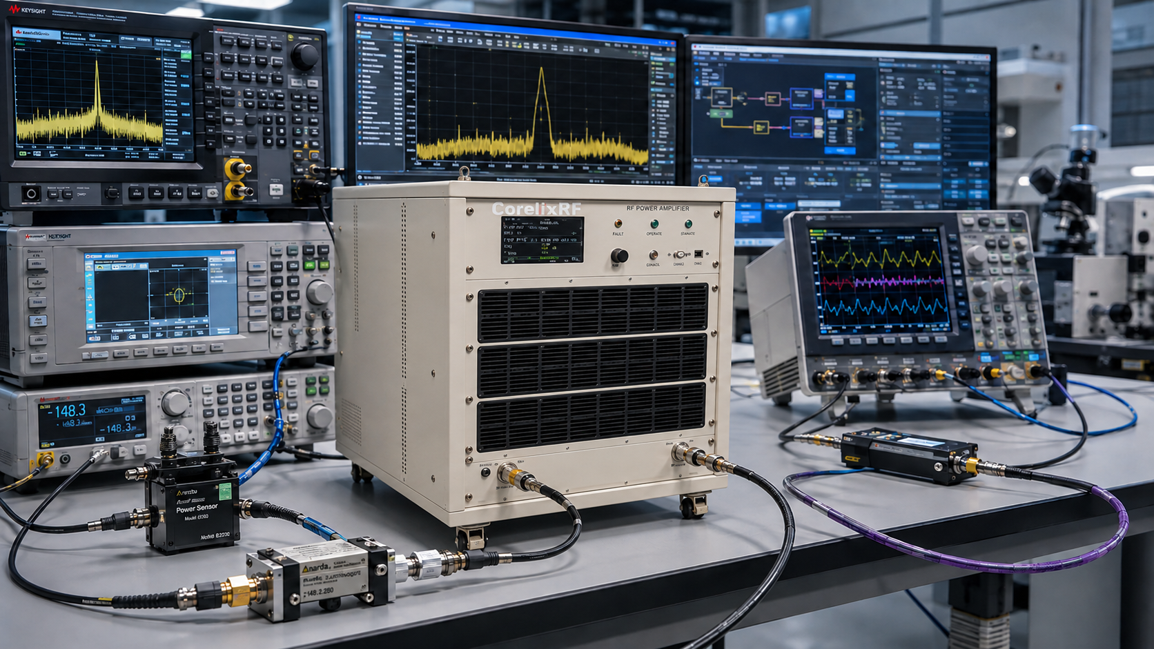
This article uses a system-integration format. CRF-PA-8000M18000M-2000W is a verified CorelixRF model from the verified CorelixRF datasheet, where it is described as a 8 GHz to 18 GHz, 2000 W solid-state RF amplifier. Because this is a very high-power microwave amplifier class, the main topic is not a simple product overview. The main topic is how to plan the RF, electrical, thermal, control, and safety interfaces before the amplifier arrives.
Integration Step 1: Define the RF Path
Start with a block diagram from signal source to load. Include the source, preamp if used, CRF-PA-8000M18000M-2000W, couplers, switches, filters, attenuators, adapters, waveguide sections, antenna, load, and power sensors. A high-power RF power amplifier cannot be safely reviewed without knowing what is connected downstream.
Integration Step 2: Build the Power Budget
The datasheet power rating is 2000 W, but delivered power depends on downstream loss. At 8 GHz to 18 GHz, loss can come from waveguide transitions, connectors, couplers, switches, and calibration hardware. Add margin for mismatch and measurement uncertainty.
Integration Step 3: Plan Cooling and Space
High-power RF systems need practical mechanical planning: cabinet location, airflow, service clearance, power input, RF connector access, grounding, and operator safety. Do not leave these questions for installation day.
Integration Step 4: Define Controls
Decide how the bench will handle RF enable, gain setting, status readback, temperature monitoring, current monitoring, forward/reverse power, alarms, and reset. A GaN RF amplifier platform can be effective in automated systems, but only if the control sequence is clearly defined.
Risk Review
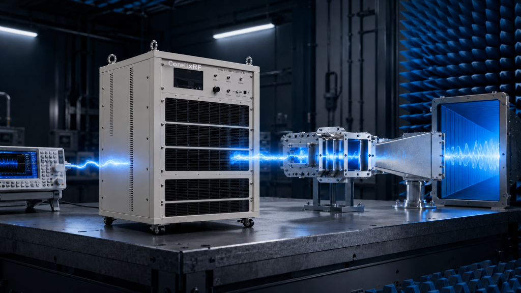
The largest risks are usually predictable: overdrive from the source, operation into an unknown load, insufficient cooling, unclear alarm handling, and inadequate test sequencing. A good integration plan includes a startup checklist and a shutdown process. It also defines who is allowed to change source level, cable routing, load condition, and software interlocks.
Information to Send CorelixRF
- System block diagram and target frequency span.
- Target load power and expected loss budget.
- Waveform, duty cycle, pulse details if applicable, and run time.
- Cooling environment, cabinet placement, and power availability.
- Connector or waveguide requirements.
- Monitoring, alarm, and remote-control expectations.
Acceptance Test Planning
Before the amplifier is integrated, define how acceptance will be checked. The plan should include frequency points, input drive settings, measured output power, gain response, reflected-power condition, alarm checks, and thermal observation during a representative run. For a high-power microwave amplifier, acceptance testing should be deliberate and documented, not improvised during installation.
The team should also decide which measurements are supplier acceptance items and which are system-level validation items. Supplier data can confirm amplifier behavior at its ports. System validation confirms the amplifier inside the real RF path, with actual cables, adapters, sensors, fixtures, cooling, and control software. Both are necessary for confident operation.
Operational Controls
Daily operation should include a startup sequence, source-level check, load confirmation, amplifier enable step, power ramp, monitoring review, and shutdown process. Operators should know what alarm states mean and what actions are allowed after a fault. These operating controls reduce avoidable downtime and protect expensive microwave hardware.
Commissioning Sequence
A commissioning sequence should begin with RF disabled. Confirm cooling, power input, grounding, load connection, sensor placement, and software status before applying drive. Then enable the amplifier at low drive and increase power in controlled steps. Record source level, measured output, reflected power if available, temperature behavior, alarm state, and any software messages.
For a high-power system, the commissioning record becomes part of the operating baseline. If the bench behaves differently later, the team can compare against the first validated setup instead of guessing. This is especially important when multiple engineers or operators will use the same amplifier chain.
Integration Responsibility Map
A system integration article should clarify responsibilities. The RF engineer owns source drive, gain margin, output measurement, load behavior, and calibration. The mechanical engineer owns mounting, airflow, connector access, and service clearance. The controls engineer owns enable logic, alarm handling, status readback, and test sequencing. Procurement owns documentation, lead-time discussion, and ensuring that any custom requirement is visible before ordering.
When these responsibilities are separated, the amplifier can be reviewed without confusion. When they are mixed together, teams often discover too late that a power supply, cooling path, connector route, or software interlock was assumed but never specified.
Final Engineering Review
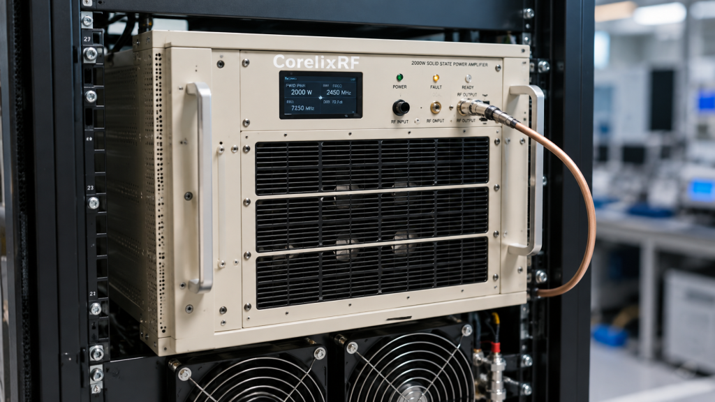
Before the article is used as a WordPress draft, the engineering message should remain conservative: the amplifier is a candidate based on verified datasheet information, not a universal fit for every system. Final selection still depends on the complete RF path, operating environment, waveform, duty cycle, control needs, and mechanical constraints. That framing keeps the content useful for engineers while avoiding unsupported promises.
FAQ
Is CRF-PA-8000M18000M-2000W verified from a local datasheet?
Yes. The source path is listed in the opening paragraph.
Why is integration planning so important?
Because 2000 W at microwave frequencies affects cooling, safety, load handling, control sequencing, and delivered power.
Should the RFQ include a block diagram?
Yes. A block diagram helps CorelixRF review power budget, interface risks, and protection requirements.
Can this become a custom system?
Yes. Use a custom RF amplifier review when the standard form does not match the integration environment.
Next Step
Prepare the RF path diagram and operating profile, then request a CorelixRF review before mechanical or procurement release.