
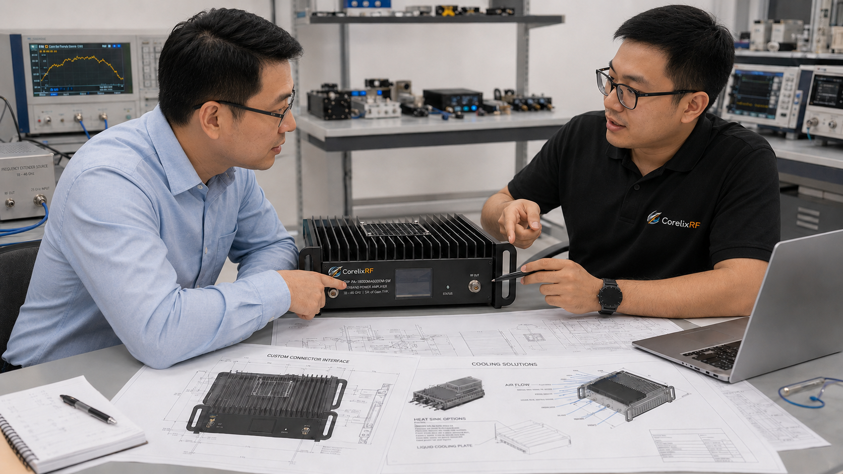
This article is written as an application note. The verified CorelixRF datasheet identifies the model and headline specifications. Instead of listing only specifications, this note explains how an engineering team might use this amplifier class in a high-frequency test setup.
Application Scenario
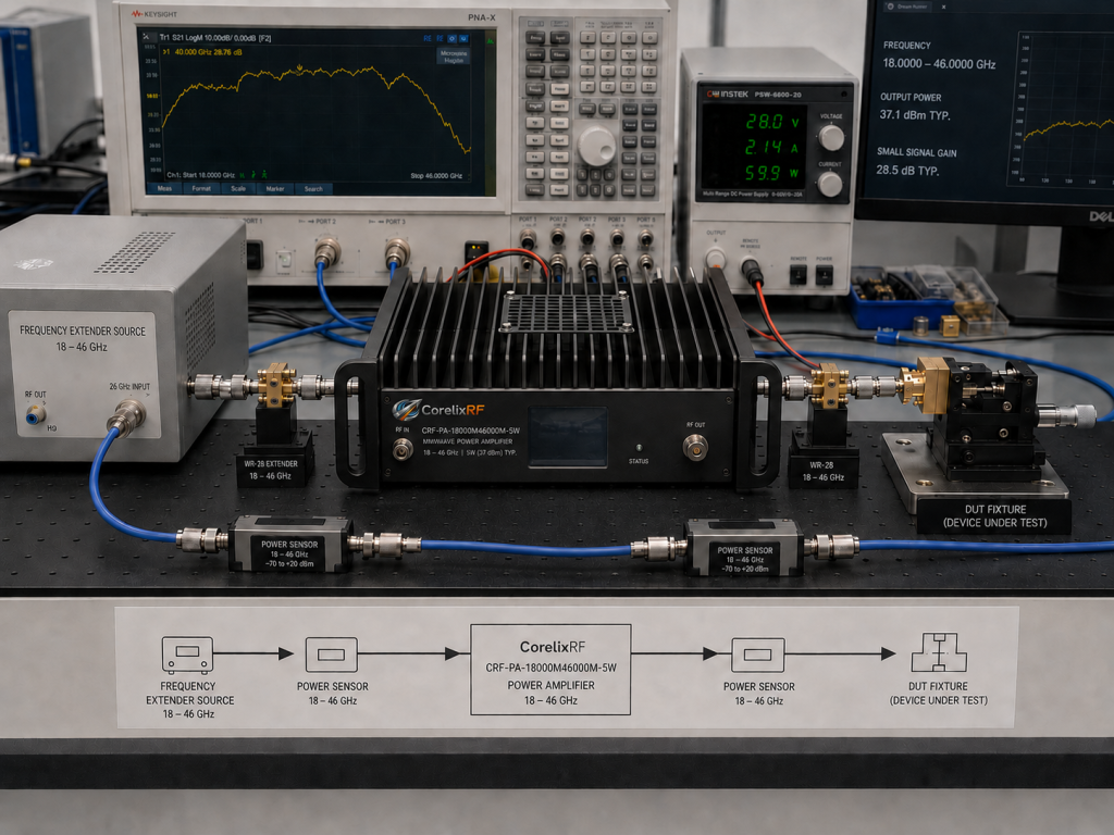
An engineer may need more RF power after a frequency extender, synthesizer chain, or compact mmWave source. The goal might be device characterization, receiver desense testing, subsystem validation, antenna-path evaluation, or controlled RF stress testing. In that situation, a mmWave RF amplifier such as CRF-PA-18000M46000M-5W can act as the power stage between the source chain and the measurement fixture.
Bench Architecture
A typical bench includes a source, frequency conversion if required, driver amplification, CRF-PA-18000M46000M-5W, a coupler, power sensor, attenuator or load, and the DUT fixture. The calibration plane must be defined carefully. At 18 GHz to 46 GHz, adapter repeatability and connector torque can change measured results.
Operating Notes
Keep source drive controlled and document the gain setting. Confirm the output path before enabling RF. Use appropriate power sensors and protect sensitive receivers or instruments. If the bench is automated, make sure the software checks load state and alarm state before enabling the amplifier.
Why the Details Matter
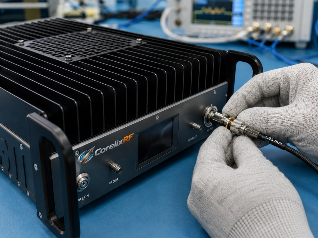
At mmWave frequencies, a small mechanical change can become an RF change. Connector wear, adapter stack length, waveguide alignment, fixture repeatability, and cable bend all affect the measurement. The amplifier is only one part of the uncertainty budget, so the test method should be stable before comparing devices or recording production data.
Recommended Review Points
- Confirm the required frequency points inside 18 GHz to 46 GHz.
- Measure or estimate loss from amplifier output to DUT.
- Choose a calibration plane and keep it consistent.
- Define safe source-drive limits.
- Plan heat removal and connector access.
- Document alarm handling and reset behavior.
When to Contact CorelixRF
Contact CorelixRF when the bench requires a different connector, enclosure, cooling path, gain-control behavior, or monitoring method. A custom RF amplifier discussion can prevent mechanical or control mismatches later.
Measurement Method
For this application note, the measurement method is as important as the amplifier. Define where power is measured, how often the calibration is refreshed, and which adapters remain fixed during a test campaign. If the amplifier is moved between benches, record the connector chain and recalibrate before comparing results.
Use conservative source settings during first bring-up. Confirm that the output path is complete, the load is rated for the expected level, and the power sensor is protected. Increase drive in controlled steps while watching measured output and any available status signals. This gives the engineering team a clean baseline before running longer automated tests.
Result Interpretation
When results change, do not assume the amplifier is the first cause. At mmWave frequencies, adapter seating, connector torque, fixture repeatability, source stability, and calibration drift can all move the result. A good application workflow separates amplifier behavior from bench uncertainty by keeping the RF path stable and documenting each change.
Recommended Bench Controls
The bench should include written controls for connector handling, calibration state, maximum source drive, load verification, and fault response. These controls do not need to be complex, but they should be visible to every operator. A simple checklist can prevent avoidable mistakes such as enabling RF before the load path is complete or comparing measurements after an adapter has changed.
For broader product planning, link this mmWave bench discussion to the wider RF power amplifier family. That helps engineers decide whether the project needs only this mmWave stage or a wider chain that includes lower-frequency driver stages, switches, couplers, or additional amplification.
Application Note Takeaway
The key takeaway for this application note is that repeatability matters more than a single impressive measurement. A successful mmWave bench should produce the same result after a cable is reconnected, after a fixture is changed, and after an operator returns the next day. That requires stable calibration practice, careful connector handling, documented source settings, and a known load path.
This model should therefore be reviewed as part of an application workflow. If the workflow is stable, the amplifier can support useful test coverage. If the workflow is loose, measurement uncertainty may hide the real behavior of the device under test.
Final Engineering Review
Before the article is used as a WordPress draft, the engineering message should remain conservative: the amplifier is a candidate based on verified datasheet information, not a universal fit for every system. Final selection still depends on the complete RF path, operating environment, waveform, duty cycle, control needs, and mechanical constraints. That framing keeps the content useful for engineers while avoiding unsupported promises.
FAQ
Is CRF-PA-18000M46000M-5W a real CorelixRF model?
Yes. It is taken from the local datasheet referenced above.
What makes this an application note?
It focuses on how the amplifier is used in a bench, not just on specification fields.
What is the biggest mmWave risk?
Measurement uncertainty from connectors, adapters, calibration plane movement, and fixture repeatability is often the biggest practical risk.
Should the RFQ include the bench layout?
Yes. A layout helps CorelixRF understand source drive, losses, monitoring, and mechanical constraints.
Next Step
Send CorelixRF the bench architecture, operating frequencies, load power target, and mechanical constraints for review.