Factory-Direct RF Power Amplifiers — 30W to 200W
GaN solid-state RF modules across 30 MHz – 6 GHz. We design and manufacture power amplifier platforms for system integrators, test engineers, and RF solution providers.
Instead of choosing from complex datasheets, we help you identify the correct power tier based on your system requirement before purchase — reducing integration risk, avoiding thermal mismatch, and ensuring stable field deployment.
Direct RF Factory Advantage
Working directly with the manufacturer removes uncertainty in RF system procurement.
You communicate directly with RF engineers — not distributors — to confirm system feasibility in one step.
→ Shorter selection cycleBefore ordering, we review output power requirement, duty cycle conditions, supply voltage stability, and thermal/cooling design — preventing integration issues after delivery.
→ Problems caught before they shipAll samples and mass production units follow identical design process, testing procedure, and burn-in validation. No performance drift between prototype and batch delivery.
→ Fewer integration surprisesEach unit is tested and validated before shipping, with a full RF performance report included.
→ Verified output before it reaches youOutput Power Defines the Entire RF System
In RF amplifier design, output power is the first selection parameter. It directly determines your DC supply requirement, thermal dissipation, mechanical platform, and system integration complexity.
Supply Voltage & Thermal Load
The power tier you choose sets your DC supply requirement and thermal dissipation level. Confirm these at the start — not after you've already integrated the wrong module.
Mechanical Platform
Output power determines the mechanical size and platform selection. Locking this early narrows a 40-model catalog to the 3–4 candidates that actually fit your chassis.
System Integration Complexity
When power tier is locked first, integration scope is clear. Engineers test against real deployment conditions — not a generic datasheet that may not reflect CW performance.
Common Engineering Risks in RF Procurement
Many project delays come from incorrect early assumptions.
Selecting a power tier that doesn't match real deployment conditions — buyers over-specify to 200W or under-specify to 100W, both creating downstream thermal or budget problems.
Datasheet values not matching CW real-world operation. Buyers discover this after integration — when there's no time to re-qualify a different model.
Thermal load is underestimated during integration. Supply voltage, current draw limits, and heatsink constraints should be locked before procurement — not after delivery.
Most RF distributors can deliver a module, but can't help you select the right power tier or review duty cycle and cooling architecture. The technical gap falls on your team.
We Eliminate RF Selection Uncertainty at the Source
Each risk above has a direct answer in how we operate as a source manufacturer.
All products are structured into five stable power tiers — 30W, 50W, 100W, 150W, and 200W — across four frequency bands. This simplifies system design and reduces selection time.
→ Standardized tiers reduce fit uncertaintyEvery unit is RF tested, burn-in validated for 48 hours, and has performance recorded per unit. Test reports are included with delivery — so you know what you're getting before you integrate it.
→ Verified performance, not just rated specsWe validate system compatibility before order confirmation — power requirement match, voltage and current feasibility, duty cycle and thermal behavior, and mechanical integration constraints.
→ Engineering review before you commitPrototype and production units follow identical process control. You communicate with the engineers who designed and built the modules — not a sales layer.
→ Technical alignment from day oneRF Power Amplifier Platform Overview
Select a power tier based on your system requirement. 100W is the most commonly used baseline for RF system integration.
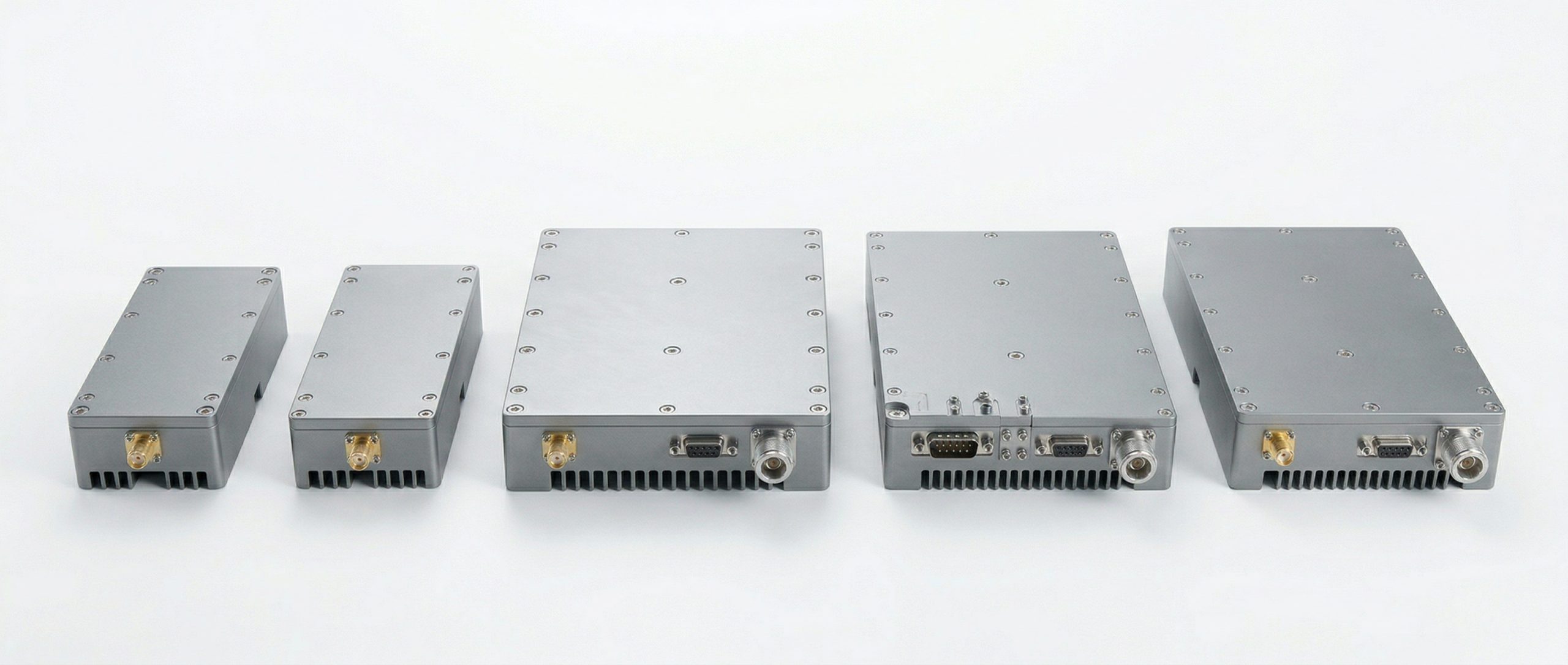
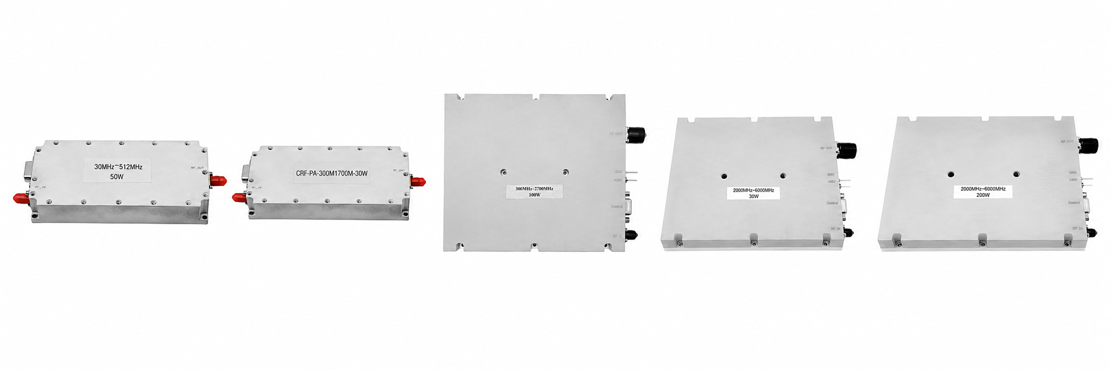
CorelixRF standard platform — 30W to 200W · 125mm & 200mm chassis · 30 MHz–6 GHz
Low power consumption and minimal thermal load. Best suited for laboratory testing and prototype validation. Not recommended for long-range field deployment.
Request 30W Quote| Model | Frequency | Pout (dBm) | Pin | VDC | Max I | Size (mm) | Actions |
|---|---|---|---|---|---|---|---|
| CRF-PA-30M512M-30W | 30–512 MHz | 45±1 | 0–8 dBm | 28V | ≤4A | 125×59×21.5 | DatasheetRFQ |
| CRF-PA-300M1700M-30W | 300–1700 MHz | 45±1 | 0–8 dBm | 28V | ≤3A | 125×59×21.5 | DatasheetRFQ |
| CRF-PA-300M2700M-30W | 300–2700 MHz | 45±1 | 0–8 dBm | 28V | ≤4A | 125×59×21.5 | DatasheetRFQ |
| CRF-PA-2G6G-30W | 2–6 GHz | 45±1 | 0–8 dBm | 36–46V | ≤4A | 125×59×21.5 | DatasheetRFQ |
Medium power RF applications. Suitable for test benches and repeaters, with moderate thermal requirements — a good balance between size and output.
Request 50W Quote| Model | Frequency | Pout (dBm) | Pin | VDC | Max I | Size (mm) | Actions |
|---|---|---|---|---|---|---|---|
| CRF-PA-30M512M-50W | 30–512 MHz | 47±1 | 0–8 | 28V | ≤9A | 125×59×21.5 | DatasheetRFQ |
| CRF-PA-300M1700M-50W | 300–1700 MHz | 47±1 | 0–8 | 28V | ≤7A | 125×59×21.5 | DatasheetRFQ |
| CRF-PA-300M2700M-50W | 300–2700 MHz | 47±1 | 0–8 | 28V | ≤9A | 125×59×21.5 | DatasheetRFQ |
| CRF-PA-2G6G-50W | 2–6 GHz | 47±1 | -1–6 | 40–58V | ≤12A | 200×158×25 | DatasheetRFQ |
System integration baseline and the most widely specified RF power tier. Best suited for field deployment systems, RF platform integration, and broadband transmit chains. Recommended starting point for most projects.
Request 100W Quote| Model | Frequency | Pout (dBm) | Pin | VDC | Max I | Size (mm) | Actions |
|---|---|---|---|---|---|---|---|
| CRF-PA-30M512M-100W | 30–512 MHz | 50±1 | 0–8 | 28V | ≤18A | 200×158×25 | DatasheetRFQ |
| CRF-PA-300M1700M-100W | 300–1700 MHz | 50±1 | 0–8 | 28V | ≤14A | 200×158×25 | DatasheetRFQ |
| CRF-PA-300M2700M-100W | 300–2700 MHz | 50±1 | 0–8 | 28V | ≤18A | 200×158×25 | DatasheetRFQ |
| CRF-PA-2G6G-100W | 2–6 GHz | 50±1 | -7–6 | 41–51V | ≤24A | 200×158×25 | DatasheetRFQ |
Higher link margin applications and an upgrade path from 100W systems, sharing the same mechanical platform. Requires thermal validation and DC supply verification.
Request 150W Quote| Model | Frequency | Pout (dBm) | Pin | VDC | Max I | Size (mm) | Actions |
|---|---|---|---|---|---|---|---|
| CRF-PA-30M512M-150W | 30–512 MHz | 52±1 | 0–8 dBm | 28V | ≤20A | 200×158×25 | DatasheetRFQ |
| CRF-PA-300M1700M-150W | 300–1700 MHz | 52±1 | 0–8 | 28V | ≤22A | 200×158×25 | DatasheetRFQ |
| CRF-PA-300M2700M-150W | 300–2700 MHz | 52±1 | 0–8 | 28V | ≤20A | 200×158×25 | DatasheetRFQ |
| CRF-PA-2G6G-150W | 2–6 GHz | 52±1 | 0–8 | 43–58V | ≤27A | 200×158×25 | DatasheetRFQ |
Long-range RF transmission for mission-critical applications — the maximum power in the standard platform. Requires a high-current power supply and a strong thermal management system.
Request 200W Quote| Model | Frequency | Pout (dBm) | Pin | VDC | Max I | Size (mm) | Actions |
|---|---|---|---|---|---|---|---|
| CRF-PA-30M512M-200W | 30–512 MHz | 53±1 | 0–8 | 28V | ≤30A | 200×158×25 | DatasheetRFQ |
| CRF-PA-300M1700M-200W | 300–1700 MHz | 53±1 | 0–8 | 28V | ≤29A | 200×158×25 | DatasheetRFQ |
| CRF-PA-300M2700M-200W | 300–2700 MHz | 53±1 | 0–8 | 28V | ≤36A | 200×158×25 | DatasheetRFQ |
| CRF-PA-2G6G-200W | 2–6 GHz | 53±1 | 0–8 | 44–54V | ≤36A | 200×158×25 | DatasheetRFQ |
How the Power Tiers Compare — and How to Choose
Compact / Evaluation
Low Current · 125mmBalanced mid-power
Standard Supply · 125mmEngineering baseline
Most Practical · 200mmHigh-output transmit
Extended Range · 200mmMaximum standard power
Max Output · 200mmLab evaluation, prototype validation, embedded low-power transmitters, compact chassis with tight thermal budgets.
Avoid if you need field-range output or plan to operate at high duty cycles.
Medium-range RF links, repeater feeds, test benches needing more headroom than 30W without full thermal infrastructure.
Avoid if your link budget requires more than modest range margin.
Most common starting point. First-stage field deployment, broadband integration, system prototyping. Shared 200mm platform enables upgrade to 150W/200W without chassis redesign.
Run a link budget first if your environment has difficult propagation.
Extended-range field applications, high-duty-cycle chains where 100W shows insufficient margin. Same chassis as 100W — minimal re-integration.
Verify your DC supply and cooling can support increased current before specifying.
Maximum range requirement, mission-critical coverage, applications where every dB of link margin counts.
Requires dedicated thermal management and high-current DC supply. Plan infrastructure before procurement.
What Procurement Teams Value About CorelixRF Modules
30W, 50W, 100W, 150W, and 200W are all maintained as standard production tiers — not custom variants. Shorter lead time, consistent specs, and predictable batch availability.
Each tier covers four discrete bands: 30–512 MHz, 300–1700 MHz, 300–2700 MHz, and 2–6 GHz. Frequency performance is tested and documented — not extrapolated.
VDC, maximum current draw, and mechanical dimensions are provided per model — not estimated. Plan your power supply and chassis before procurement, not after delivery.
Direct access to factory engineers for thermal review, interface adaptation, and integration support. Technical questions reach the people who built the product — not a distributor relay.
Sample units and production batches follow the same manufacturing and QC process. Performance validated on samples translates directly to batch deliveries.
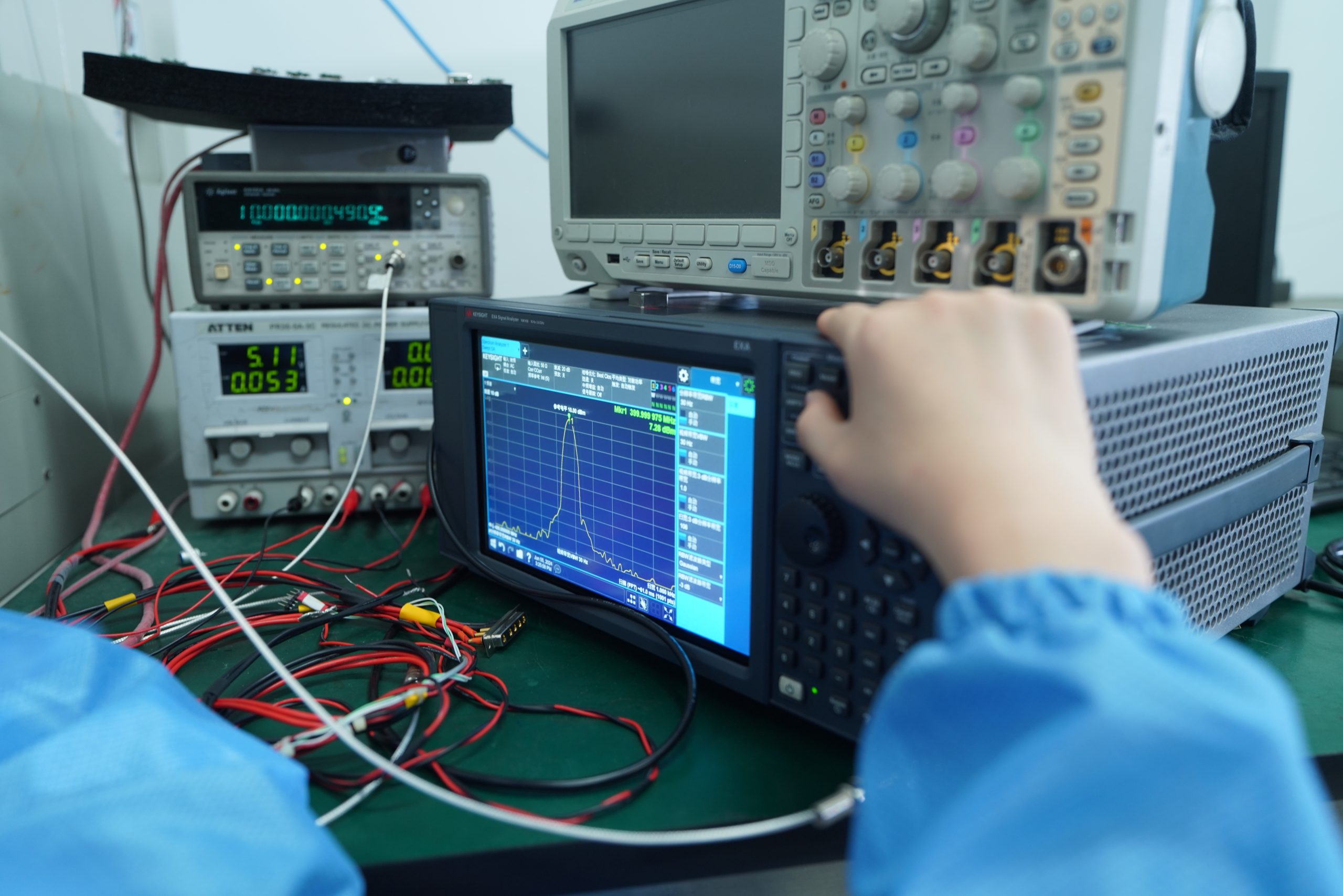
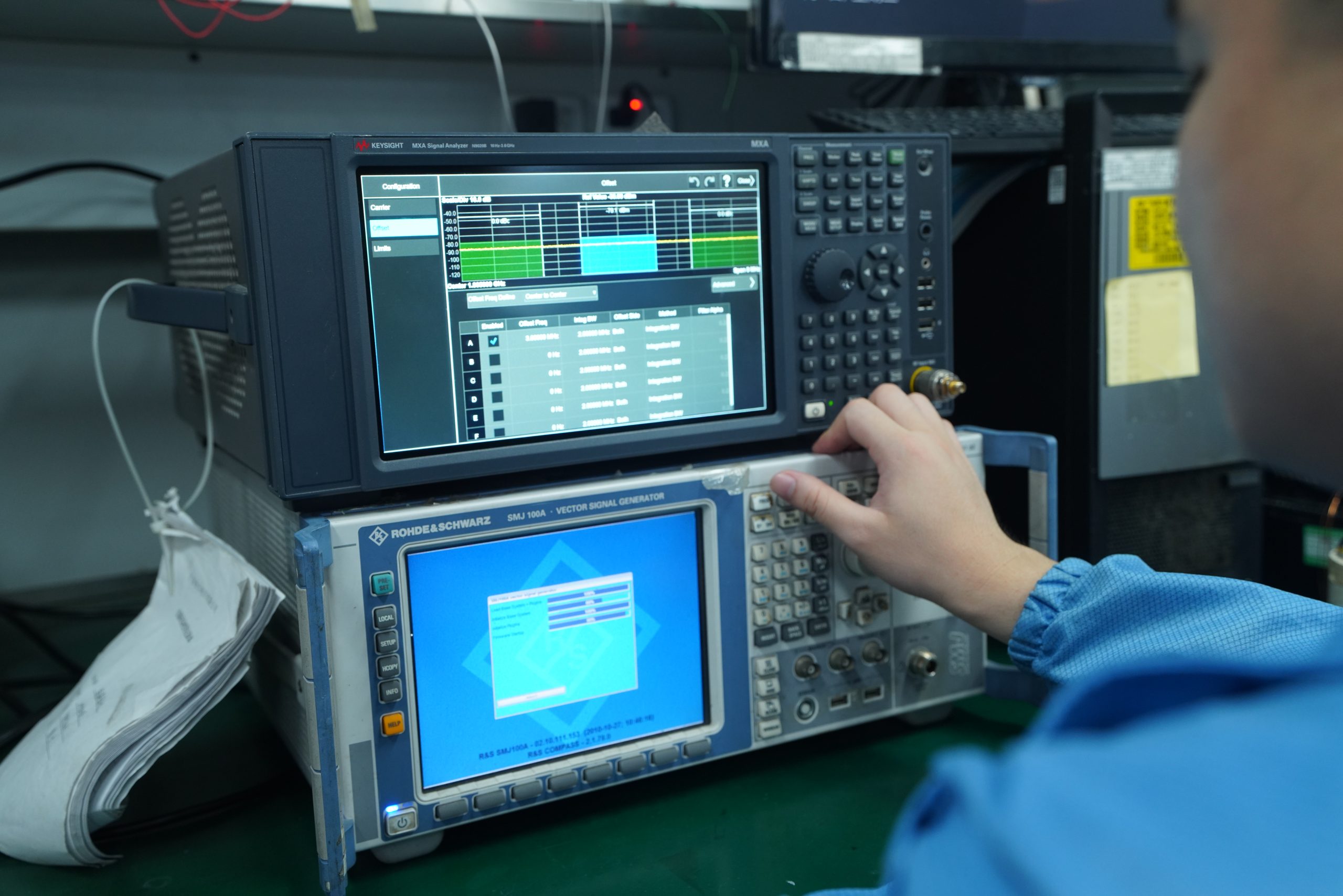
Every unit ships with a verified RF test report. Burn-in, performance verification, and documentation are factory-standard — not optional add-ons at extra cost.
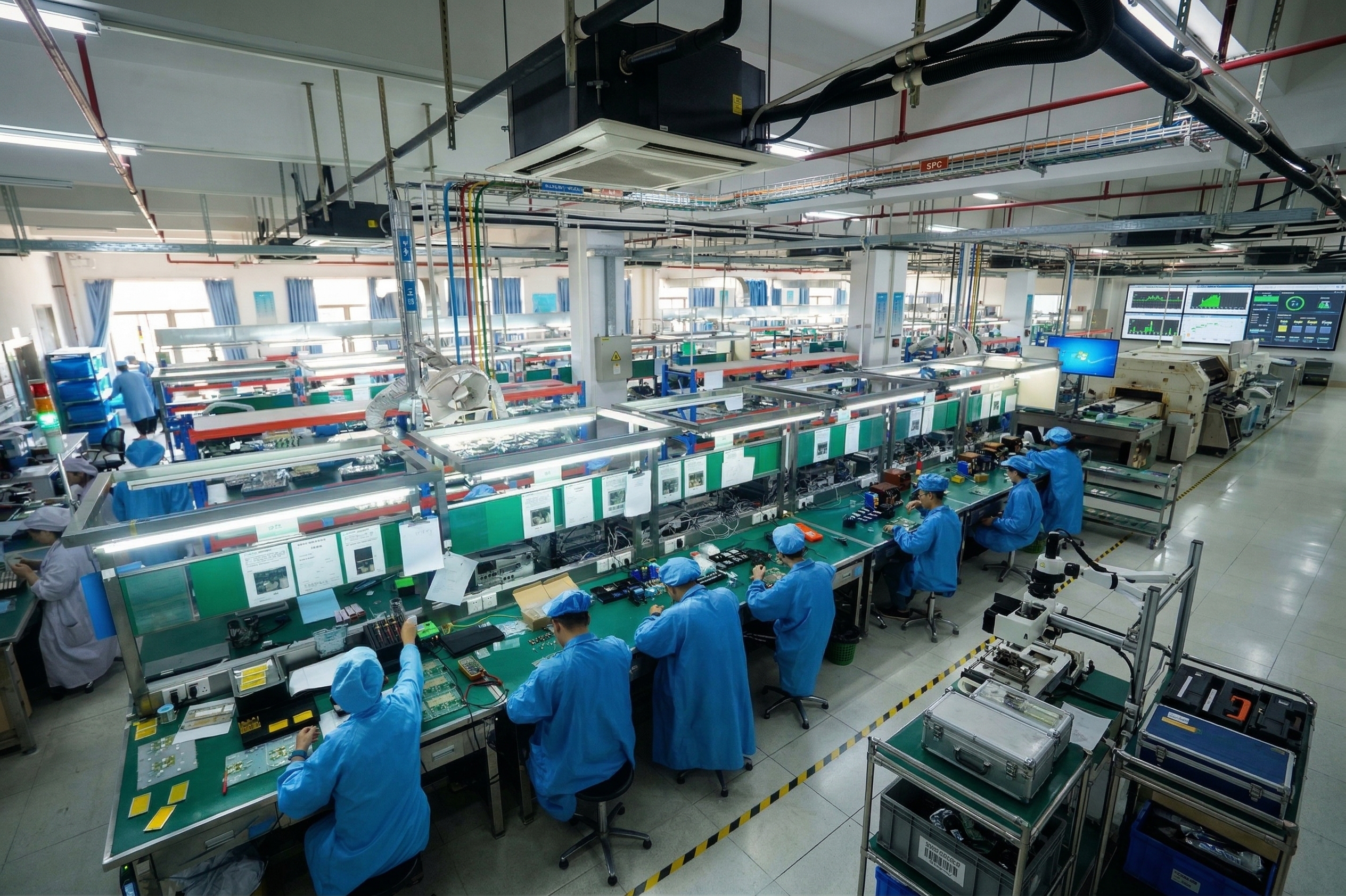
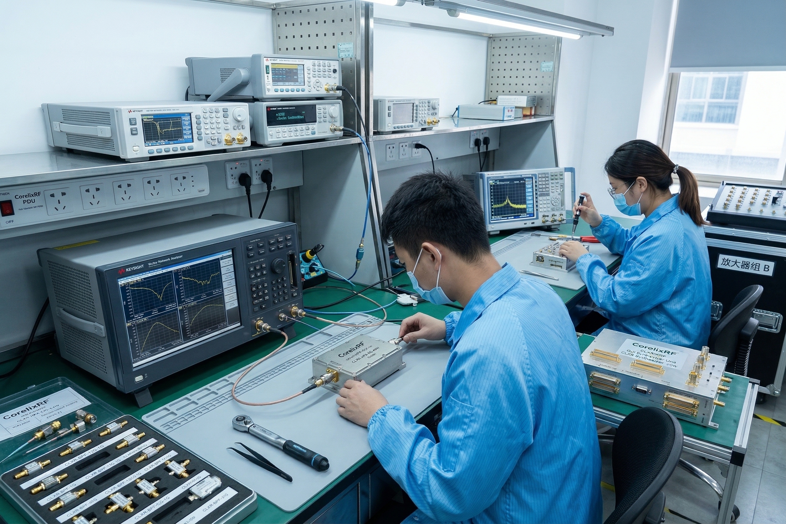
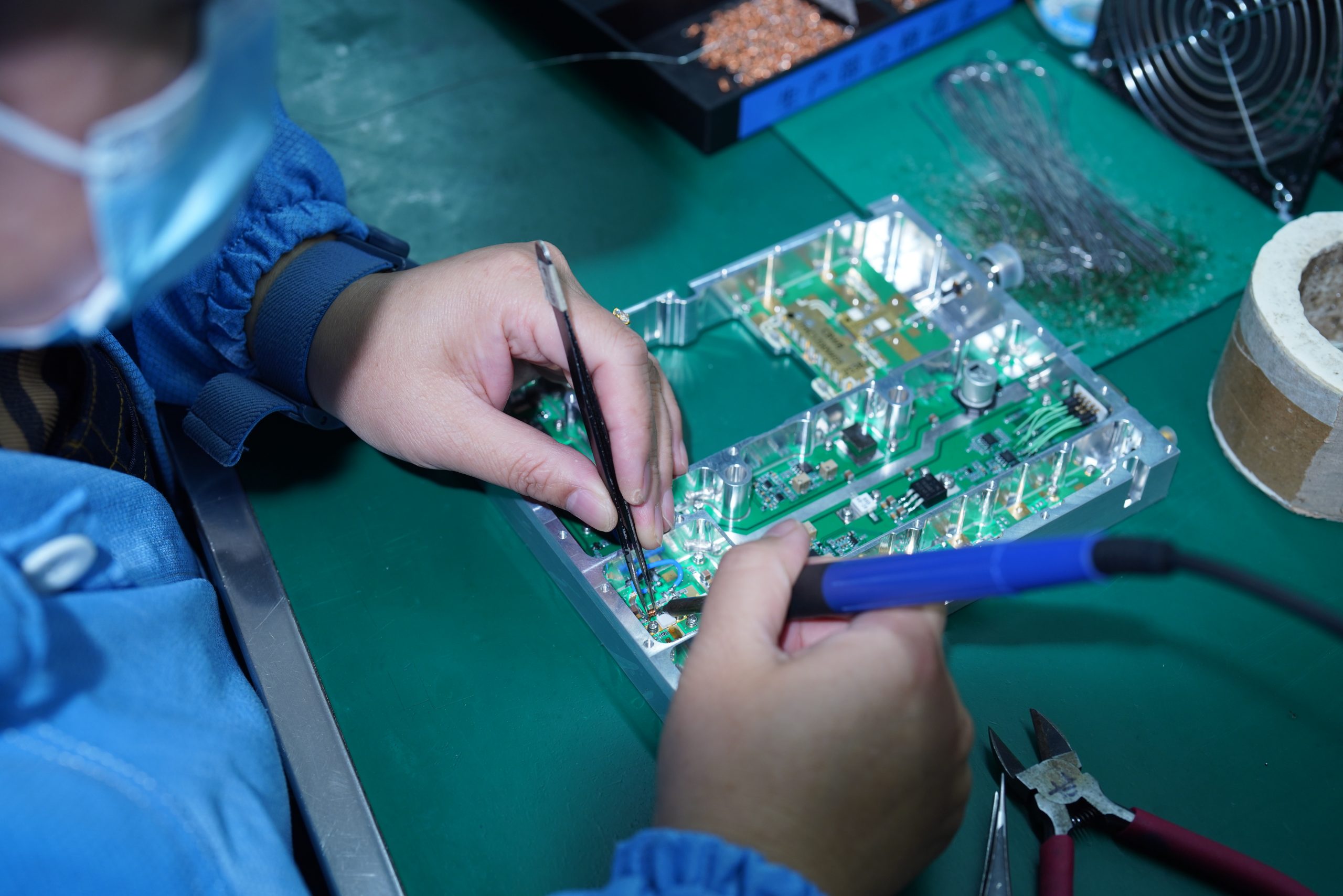
Left: SMT assembly & solder control · Right: RF output verification per unit
Manufacturing & Validation Process That Supports Stable Delivery
Repeatable output starts with a repeatable process. CorelixRF's manufacturing and QC workflow is designed to deliver consistent performance from first sample to final batch.
Typical Use Cases by Power Tier
Different output power levels serve different deployment contexts. Here is where each tier is most commonly specified.
Used for RF validation, prototype testing, and controlled lab environments. Low thermal overhead suits setups without dedicated cooling infrastructure.
Automated test equipment (ATE) TX chains and EMC test setups requiring repeatable, calibrated output.
Used in RF subsystem integration and field deployment platforms. Shared 200mm platform simplifies future upgrades to 150W or 200W.
Platform integration for larger transmit chain assemblies. Factory engineering support helps align supply voltage, cooling path, and connector interfaces.
Used in long-distance communication and high-margin RF links. Requires dedicated thermal management planning and verified DC supply headroom.
Maximum power in the standard platform for mission-critical applications. Specified from the design phase — not retrofitted.
Common Procurement Mistakes When Buying RF Power Amplifiers
These are the patterns we see most often cause integration delays or field performance shortfalls. Knowing them in advance saves significant project time.
Rated output power is measured under specific duty cycle and temperature conditions. A module specified at 100W CW will behave very differently at 50% duty cycle — confirm both before specifying.
Datasheet values represent lab conditions. Request actual test reports and ask the supplier to confirm performance under your specific duty cycle and thermal environment before procurement.
Supply voltage, maximum current draw, and cooling method must be locked before the purchase order. Late discovery of supply rail mismatches delays deployment by weeks — sometimes months.
The lowest-price module that doesn't match your power tier, frequency, or interface requirements costs more in re-qualification time than the price difference. Ask for engineering review before committing.
What Our Factory Background Means for Your Project
CorelixRF is the manufacturer — not a distributor or reseller. The practical implications of that distinction show up at four specific points in every procurement cycle:
Engineering-to-engineering communication — your technical requirements reach the design team directly. No translation layer, no spec drift between what you ask for and what gets built.
Accelerated sample-to-production path — R&D and production share the same facility. Performance validated on a sample transfers directly into your production batch without re-qualification risk.
Front-end technical review at no cost — before a purchase order is placed, factory engineers can review your duty cycle, VDC rail, cooling path, and connector requirements. Conflicts get caught early, not after delivery.
Export-ready documentation as standard — CE, RoHS, ISO 9001, per-unit RF test reports, and commercial invoicing for international shipment are part of every delivery, not optional extras.
What "direct factory" means in practice
Selection → confirmed faster
Power tier, frequency band, and supply requirements can be locked in a single technical conversation — not over three rounds of email with a sales team.
Sample → batch with no surprises
The module you test is made the same way as the batch you order. Same process, same QC steps, same test protocol.
Scaling → without chassis redesign
100W, 150W, and 200W share the same 200mm mechanical platform. Upgrading power tier doesn't require a new mechanical integration.
Problems → surface before they ship
48-hour burn-in and full RF verification per unit means field failures caused by factory defects are rare. If something fails burn-in, it never ships.
Factory Delivery Evidence & Customer Trust Signals
Dedicated RF amplifier module development — same engineering team, same production facility
Active project deliveries across Asia-Pacific, Europe, Americas, and the Middle East
From single evaluation units to multi-batch production orders — all through the same 46-step QC process
Project teams returning for follow-on orders — the most reliable performance signal we can show
Workshop & Packing Video Evidence
Production line footage, RF test bench operation, and export packing documentation — showing what happens to each unit before it ships.
Who Buys From CorelixRF — Customer Profile
RF System Integrators
Teams building multi-component RF chains who need a reliable amplifier source with technical alignment at the component level. Common use: 100W–150W for field platform integration.
Defense & Tactical Communication Teams
Project procurement for platforms requiring verified output performance, consistent batch quality, and full test documentation. Common use: 100W–200W across 30–3000 MHz.
Test & Measurement Engineers
ATE developers and EMC test facility builders who need predictable, stable RF output at known power levels for repeatable test conditions. Common use: 30W–100W evaluation and production test.
Representative Project Scenarios
Europe · RF System Integrator · 100W · CRF-PA-300M2700M-100W
Platform integration, 300–2700 MHz, 40-unit batch
100W broadband amplifier used in 300–2700 MHz system integration for a mobile platform. Pre-purchase engineering review prevented thermal mismatch under 30% duty cycle at 45°C ambient. Delivered batch consistency confirmed across 40 units, with no spec changes between sample and production.
Asia-Pacific · ATE Manufacturer · 50W · CRF-PA-30M512M-50W
Production test bench, 30–512 MHz, ongoing supply
50W amplifier used in automated RF test bench systems for a government electronics supplier. Required tight amplitude stability (≤±0.5 dB flatness) across the 30–512 MHz band. Multiple repeat orders — now in the third purchase cycle — confirmed performance consistency.
Middle East · Defense Procurement · 200W · CRF-PA-300M1700M-200W
Long-range coverage platform, 300–1700 MHz, 28VDC supply
200W system used for an extended-range RF coverage platform at 300–1700 MHz. Link budget calculations defined the requirement before procurement — no room to step up later. Factory verified 28VDC rail compatibility and thermal feasibility before PO, with per-unit RF test reports and export documentation included.
North America · RF Engineering Lab · 30W → 100W · CRF-PA-2G6G Series
Lab characterization to system integration, 2–6 GHz
Started with CRF-PA-2G6G-30W for bench-level signal chain characterization at 2–6 GHz. After validation confirmed gain flatness and noise performance, the lab stepped up to CRF-PA-2G6G-100W for the integration phase. Same platform design — same connector positions and footprint — allowed a seamless transition with no mechanical redesign.
Compliance & Quality Certifications
Expand the RF Signal Chain
RF power amplifiers work as part of a larger transmit chain. CorelixRF also supplies complementary RF building blocks for integrated projects.
SDR Signal Sources
Software-defined radio signal generation for broadband transmit chains and test setups.
View SDR Category →Broadband Antennas
Wideband antennas matched to the frequency bands covered by CorelixRF power amplifier platforms.
View Antenna Category →Custom RF Solutions
Project-specific RF module configurations for frequency ranges, power levels, or form factors outside standard tiers.
View Custom Solutions →Also Browse By
RF Power Amplifiers by Frequency Band
If frequency band is your primary constraint — rather than output power — browse directly by band to see all available models and power tiers within that range.
Jump To
Find the Right Series for Your Scenario
Not sure which power tier fits? These scenario-based links go directly to the model groups most commonly specified for each use case.
Frequently Asked Questions
Request RF Engineering Review
We will recommend the correct RF power tier based on your system requirements and integration conditions.
Request Technical Quote