
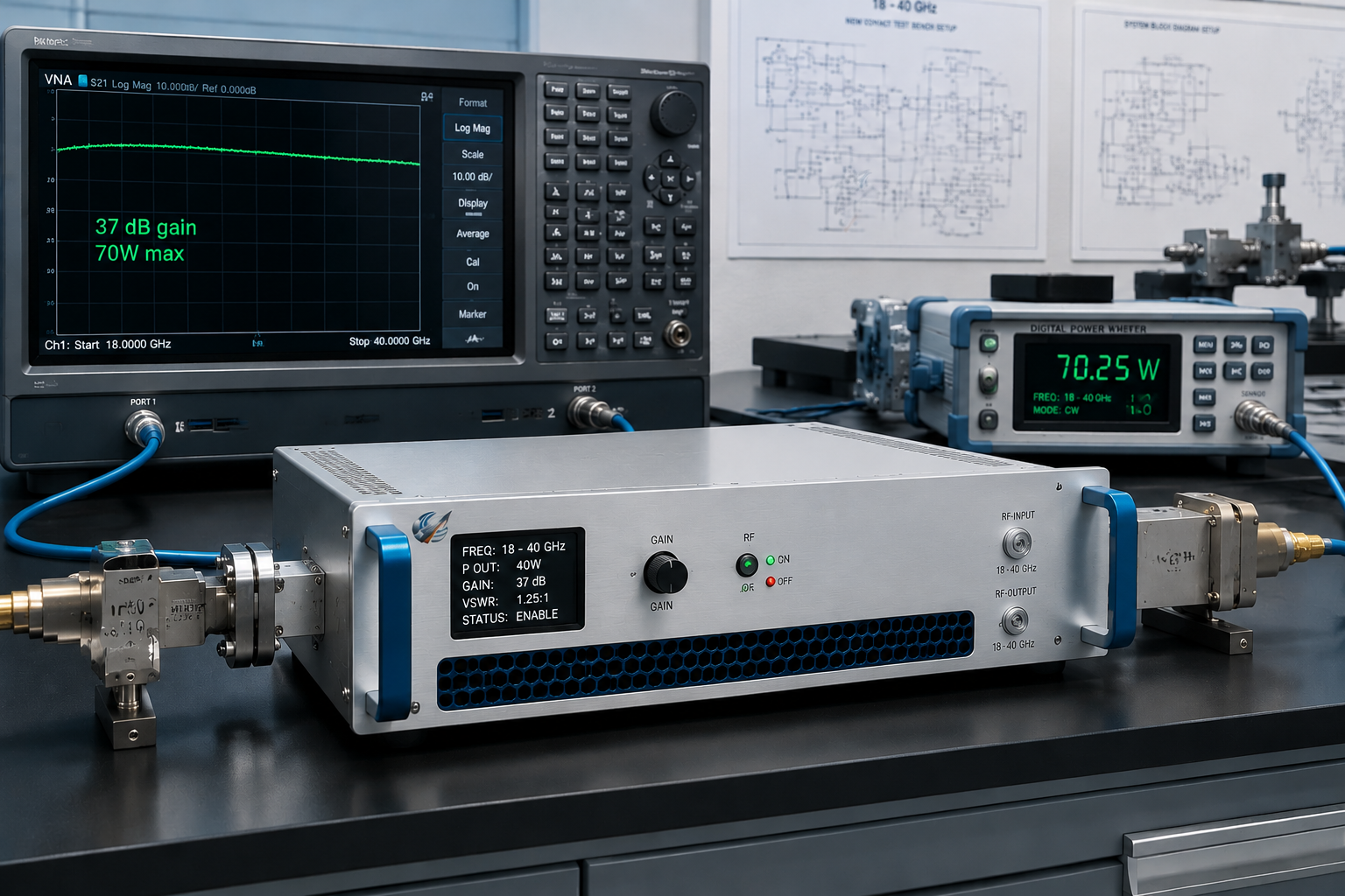
An 18-40 GHz RF power amplifier is selected very differently from a lower-frequency broadband amplifier. At K-band and Ka-band frequencies, connector loss, waveguide transitions, rack cooling, gain flatness, measurement setup, and control interface can affect the delivered RF power as much as the rated output specification. For engineers and technical buyers, the right question is not only “How many watts does the amplifier provide?” It is whether the complete mmWave RF chain can support the required output under real test or integration conditions.
CorelixRF organizes its 18-40 GHz amplifier platform around standard 5 W, 20 W, 40 W, and 70 W classes, with project-based review for custom frequency windows, connector options, waveguide output, control interface, rack structure, and cooling design. The CRF-PA-18000M40000M series is the baseline full-band model family for engineering review.
Why 18-40 GHz Amplifier Selection Is Different
At lower RF frequencies, cable loss and adapter choices still matter, but they are often easier to manage. At 18-40 GHz, every transition in the RF path can change system margin. A 2.92 mm connector, a waveguide output, an adapter stack, a test cable, and a load can all affect the measured result.
This means the amplifier should be reviewed together with the measurement environment. Buyers should define whether the amplifier will be used for radar front-end validation, mmWave communication testing, SATCOM-related evaluation, RF test and measurement, aerospace RF validation, or custom system integration.
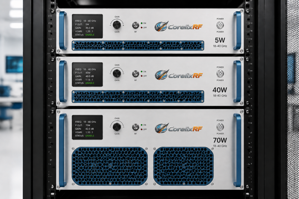
Standard Power Classes
CorelixRF lists four standard full-band review classes for 18-40 GHz:
CRF-PA-18000M40000M-5W: 18-40 GHz, 5 W, 37 dB gain, 2.92 mm-F output, 19-inch 3U enclosure.
CRF-PA-18000M40000M-20W: 18-40 GHz, 20 W, 43 dB gain, WRD180 output, 19-inch 3U enclosure.
CRF-PA-18000M40000M-40W: 18-40 GHz, 40 W, 50 dB gain, WRD180 output, 19-inch 4U enclosure.
CRF-PA-18000M40000M-70W: 18-40 GHz, 70 W, 49 dB gain, WRD180 output, 19-inch 8U enclosure.
These classes should be treated as starting points for engineering review. The final recommendation depends on output behavior across the required frequency range, control interface, cooling method, connector path, and system documentation needs.
Connector and Waveguide Review
CorelixRF lists 2.92 mm-F input and model-dependent 2.92 mm-F or WRD180 output configurations. This is important because the output interface affects cable routing, waveguide transitions, test fixture design, and delivered power at the device under test.
If the amplifier is used in a test bench, specify the planned cable type, waveguide transition, load, coupler, attenuator, and measurement instrument. If it is used in an integrated system, specify the output path and mechanical constraints. At mmWave frequencies, a small interface decision can become a major integration issue.
Rack, Cooling, and Control
The 18-40 GHz platform includes 19-inch 3U, 4U, and 8U rack formats depending on power class. Control interface options include RS485, LAN, and GPIB depending on configuration. These details matter for automated test systems, remote racks, and system-level integration.
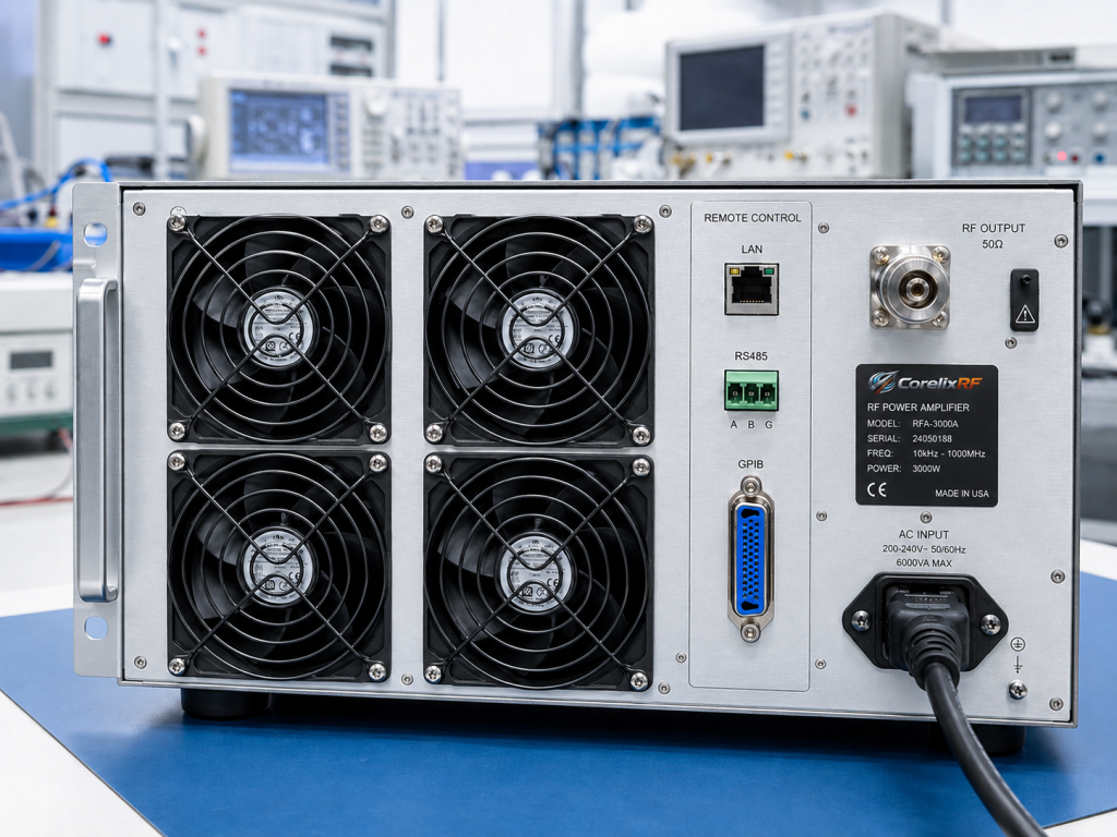
A 70 W mmWave amplifier in an 8U rack format is a different project than a 5 W compact 3U lab amplifier. Buyers should review cabinet space, airflow path, power supply, remote control requirements, and test data needs before quotation.
FAQ
What is the 18-40 GHz RF amplifier platform used for?
It is used for mmWave communication testing, radar and RF sensing validation, SATCOM-related ground terminal testing, aerospace RF validation, and high-frequency RF test benches.
What power classes are listed?
CorelixRF lists 5 W, 20 W, 40 W, and 70 W standard full-band classes for the 18-40 GHz platform.
Why does the RF output connector matter?
At mmWave frequencies, connector and waveguide transitions affect delivered power, mismatch, measurement repeatability, and system integration.