
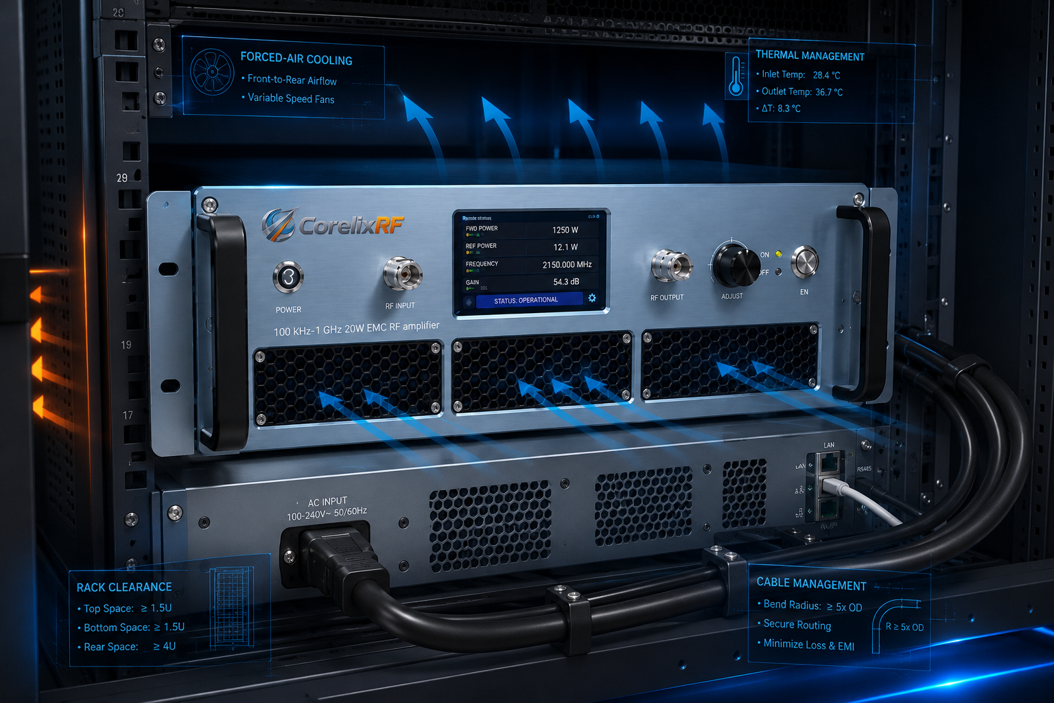
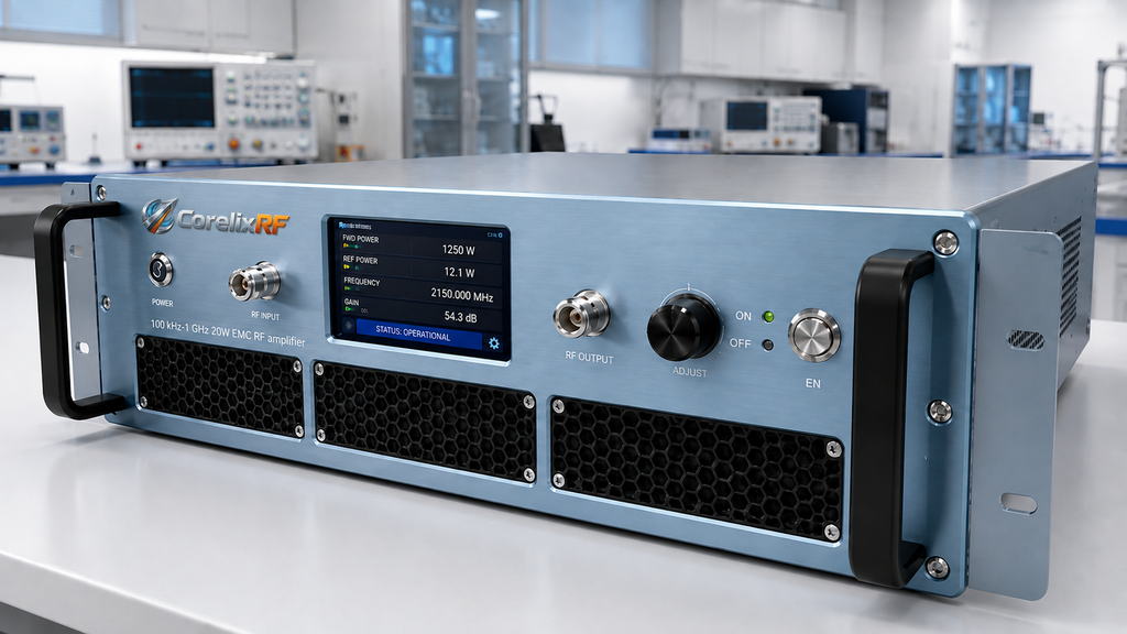
A 100 kHz-1 GHz 20W EMC RF amplifier fills a useful gap between low-power signal generation and high-power EMC drive systems. The CorelixRF CRF-PA-100K1000M-20W covers 100 kHz to 1,000 MHz with 20 W minimum rated output power, 45 dB minimum small-signal gain, N-Female input and output connectors, RS485/LAN control, AC 220 V input, forced-air cooling, and a 19-inch 3U rack-mount structure.
This article is written as setup notes for a pre-compliance or engineering lab. The intent is not to promise a complete certification outcome. It is to help engineers define a repeatable RF path before they move to higher power, formal EMC work, communication testing, or RF interference system-level validation. The datasheet supports test and measurement instrumentation, communication systems, RF interference or EW testing, and aerospace control applications.
Symptom 1: Output Changes Across the Sweep
The 100 kHz to 1 GHz span is wide enough that the fixture, cable, coupler, load, antenna, and calibration method can change the real result. A buyer searching for a broadband RF amplifier should avoid treating this as one flat bench condition. Record the frequency points, intended load, cable loss, directional device, and measurement reference plane before the first RF power step.
The amplifier lists -3 dB to +3 dB small-signal gain flatness and 20 dB gain-control range. Those values are useful for a pre-compliance sweep, but the operator still needs a correction table for the external chain. If the same amplifier is used with several antennas or fixtures, keep a separate worksheet for each configuration.
Symptom 2: Input Drive Is Too Easy to Overlook
The listed maximum input power is 0 dBm. With 45 dB minimum gain, a casual source-level mistake can overload the test path. Start with the RF source disabled, connect a rated 50 ohm load or validated test fixture, set the gain state, and increase the drive slowly while recording output power, current, temperature, and alarm state.
- Set a source power limit before connecting the amplifier input.
- Verify N-Female input and output adapter ratings across the band.
- Record forward and reverse power if that option is included.
- Capture current and temperature at low, mid, and high test bands.
- Stop the sweep if load mismatch or unexpected current behavior appears.
Troubleshooting rule: treat each setup change as a possible root cause, not as a casual adjustment. If the antenna, fixture, coupler, cable, or rack position changes, add a new notebook entry with the reason for the change and the measured effect. This voice is intentionally observational, because pre-compliance work often fails when small setup details are not written down.
Symptom 3: Temperature Rises During Long Runs
The model uses a 19-inch 3U rack-mount form factor with a typical weight of 20 kg. That matters for a pre-compliance bench because airflow, rear-panel access, rack grounding, AC power routing, and cable bend radius all influence day-to-day repeatability. Forced-air cooling should not be blocked by temporary bench placement or dense adjacent equipment.
For a small lab, the amplifier may be moved between benches. If that happens, keep the mechanical drawing and setup sheet with the unit. Moving the RF path without updating the test record can make a later comparison meaningless.

Symptom 4: Fault Data Is Missing
The datasheet lists real-time temperature monitoring, real-time current monitoring, optional forward/reverse power monitoring, optional LAN remote monitoring, alarm and fault protection, over-temperature protection, over-drive protection, over-voltage protection, and VSWR protection and alarm functions. For pre-compliance work, forward/reverse power monitoring can be valuable because mismatch is often part of the learning process.
If the lab needs GPIB programmable control, LAN remote operation, or a project-specific protocol, include that request in the RFQ rather than assuming it is present. CorelixRF supports project review for control protocols and documentation, and the safest path is to define those needs through custom RF amplifier development before the order is frozen.
Symptom 5: Results Are Hard to Repeat
The pre-compliance record should include model, frequency points, input drive, gain setting, measured output power, load or antenna condition, current, temperature, reflected-power behavior, and any alarm events. Keep the record simple enough that another engineer can repeat it without asking how the setup was built.
When the test grows beyond a 20 W setup, the same record becomes the handoff file for a higher-power RF power amplifier. That is the real value of using a structured setup note: it reduces guesswork when the project moves from discovery to procurement.
Do not add unsupported claims about certifications, inventory, or customer projects in the purchase file. The local datasheet supports ISO 9001 quality management, RoHS-compliant materials where applicable, and project-based regulatory documentation support upon request according to configuration, market, and application.
Troubleshooting Closeout
The handoff from engineering exploration to purchasing should be narrow and evidence based. Attach the frequency worksheet, fixture notes, drive limits, selected monitoring options, rack airflow condition, and any early mismatch observations. That gives CorelixRF enough context to recommend whether the 20 W LDMOS platform is appropriate or whether a higher-power EMC amplifier should be reviewed.
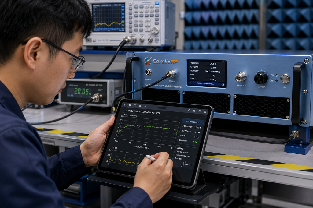
The same handoff should identify any uncertainty that remains. For example, a team may know the upper frequency and fixture type but not the final antenna, chamber, or duty condition. Calling out those open items is better than hiding them behind a generic request for an EMC amplifier. It protects the buyer from under-specifying the test chain and helps the supplier respond with a configuration that can be validated.
FAQ
What frequency range does the CRF-PA-100K1000M-20W cover?
It covers 100 kHz to 1,000 MHz.
What output power is listed?
The datasheet lists 20 W minimum rated solid-state RF output power.
What RF connectors are listed?
The listed RF input and output connectors are N-Female.
Is this a certification guarantee?
No. It is a pre-compliance and engineering test amplifier; formal compliance depends on the complete test setup, method, and applicable standard.