
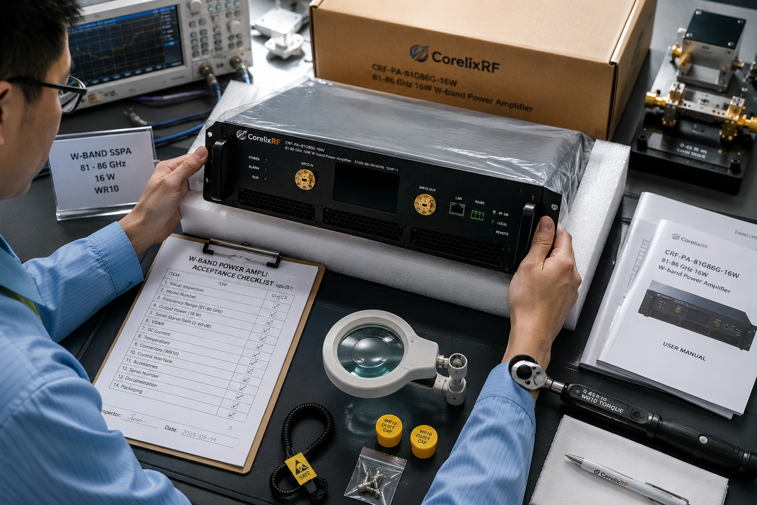
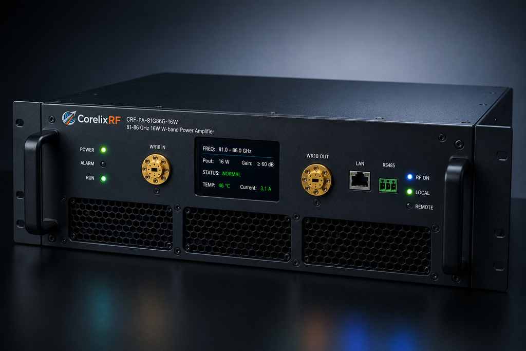
These handover notes are for engineers moving an 81-86 GHz 16W W-band power amplifier from procurement review into bench or rack integration. The CorelixRF datasheet identifies the unit as CRF-PA-81000M86000M-16W, with 81 to 86 GHz frequency coverage, 16 W rated output power, 43 dB minimum small-signal gain, WR10 input and output on the front panel, RS485/LAN control, AC 220 V input, forced-air cooling, and a 19-inch 3U form factor.
At W-band, the handover should focus on waveguide handling, calibration plane, load condition, control interface, monitoring, and documentation. The amplifier can meet its electrical specification and still be difficult to validate if the lab treats WR10 hardware like a normal coaxial jumper. Mechanical alignment and measurement method are part of the RF result.
Notebook Entry: Model Name Cross-Check
The file name uses CRF-PA-81G86G-16W, while the extracted datasheet text identifies the model as CRF-PA-81000M86000M-16W. Both refer to the same 81-86 GHz 16 W product in this source set. For internal procurement, quote, and acceptance records, choose one naming convention and cross-reference the other so receiving, engineering, and purchasing do not treat them as different units.
The frequency range should be written as 81-86 GHz and the output power as 16 W. Avoid adding unsupported claims about inventory, certification, customer use, or availability. The datasheet supports GaN SSPA technology, monitoring and protection functions, and project-based documentation support.
Notebook Entry: WR10 Reference Plane
The listed RF input and output are WR10, front panel. That makes waveguide condition, flange alignment, fastener torque, adapter cleanliness, and calibration plane critical. A small mechanical issue can change measured output power, reflected power, or apparent gain. The receiving checklist should include visual inspection, connector protection, waveguide orientation, and the exact load or antenna path used for first RF power.
- Inspect WR10 interfaces before removing protective covers.
- Define the input and output calibration planes in the test record.
- Use waveguide hardware rated for the expected power and band.
- Record flange or adapter changes between test points.
- Stop testing if reflected-power behavior changes unexpectedly.
Notebook Entry: Measurement Evidence
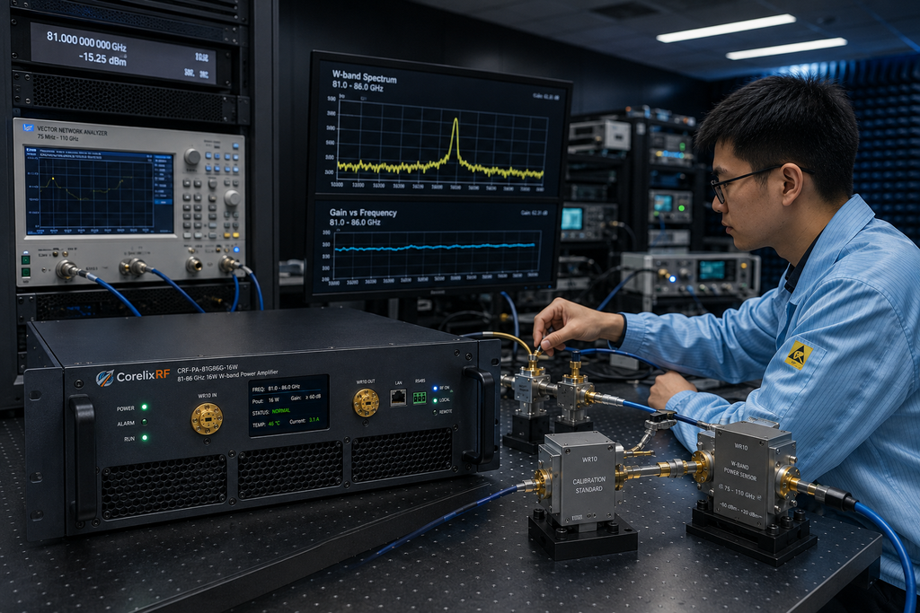
The datasheet lists 43 dB minimum small-signal gain, -10 dB to +10 dB gain flatness, 15 dB gain control range, -20 dBc harmonics, and -60 dBc spurious performance. At 81-86 GHz, measurement uncertainty can be meaningful, so acceptance should use the shipped configuration’s measured data and a clearly documented test setup.
CorelixRF’s contact page asks for frequency, output power, operating mode, load condition, cooling, connector preference, and documentation need. That is especially relevant for a high frequency RF amplifier because the practical question is not only whether the amplifier covers the band, but whether the whole measurement path is valid.
Notebook Entry: Rack and Control Ownership
The unit is listed as a 19-inch 3U forced-air configuration with AC 220 V +/-10%, 50/60 Hz supply. Before installation, assign ownership for rack airflow, AC power, remote control, alarm monitoring, and data logging. The datasheet lists real-time temperature monitoring, real-time current monitoring, optional forward/reverse power monitoring, over-temperature protection, over-drive protection, over-voltage protection, and VSWR protection and alarm functions.
RS485 and LAN control are listed. If the host software must read alarms or operating data, confirm the protocol and command behavior before field handover. If GPIB, input power detection, or other project-specific controls are needed, route the request through custom RF development before the final configuration is frozen.
Notebook Entry: RFQ Archive
The RFQ archive should contain the datasheet, final mechanical drawing, control notes, waveguide path diagram, source power plan, load rating, measured test data, and acceptance procedure. It should also state whether optional forward/reverse power monitoring is included. This avoids future confusion when the amplifier is moved, retested, or reused in another W-band setup.
For buyers comparing lower millimeter-wave options, a 18-40 GHz RF amplifier page may help frame high-frequency platform review, but the 81-86 GHz unit should be treated as a WR10 W-band integration project. The final step is to send the complete operating context to CorelixRF so the factory review can match the real RF chain.
Receiving Checklist
Receiving should not unpack and energize the amplifier as a routine instrument. The team should confirm the purchase model, cross-reference the model naming, inspect the WR10 interfaces, check the 19-inch 3U rack plan, verify AC 220 V availability, and confirm that the control connection is ready before RF testing. If the amplifier is shipped with a project drawing or test data, those documents should be stored with the acceptance file before the unit moves to the lab.
A strong receiving checklist also assigns ownership. One person owns waveguide hardware, one owns the RF source and measurement path, one owns rack power and airflow, and one owns control software. Clear ownership matters because W-band measurements are sensitive to small setup changes, and repeated retesting without a stable configuration can consume significant engineering time.
The final handover package should include a short change-control note. If the WR10 path, source drive plan, rack location, control protocol, or load changes, the team should repeat the relevant acceptance steps instead of relying on the original factory data alone. That keeps the amplifier record useful after the first installation.
FAQ
What frequency range does this W-band amplifier cover?
The datasheet covers 81 GHz to 86 GHz.
What output power is listed?
The rated output power is listed as 16 W.
What RF interfaces are used?
WR10 input and WR10 output are listed on the front panel.
What mechanical format is listed?
The datasheet lists a 19-inch 3U forced-air rack configuration.