
A 1000-2000 MHz pulsed RF amplifier is specified differently from a broadband CW laboratory amplifier. The project usually has a defined pulse width, duty cycle, peak power target, control timing requirement and cooling structure. If those details are missing, the quotation may look complete but still fail to answer whether the amplifier can operate in the real L-band radar or RF validation environment.
CorelixRF’s public pulsed amplifier page lists CRF-PA-1000M2000M-1500W as a representative high-power L-band platform. The table shows 1000-2000 MHz frequency coverage, 1500 W rated output, 62 dB gain, a 1-50 microsecond pulse condition at 5 percent duty cycle, RS485/LAN control and a 19-inch 5U structure around 35 kg. Those values make the platform suitable for engineering review where high peak RF output and rack-level integration are required.
Why Pulse Conditions Drive the RFQ
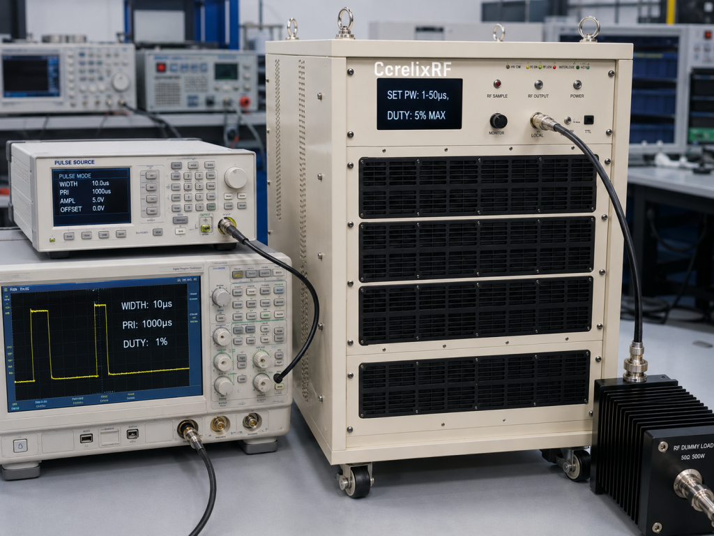
Peak output power is only meaningful when it is connected to pulse condition. A 1500 W pulsed RF amplifier used with short pulses and limited duty cycle is not the same selection problem as a continuous-wave amplifier. The source waveform, repetition frequency, pulse width, duty cycle, rise/fall expectations and operating sequence should be included in the first inquiry.
The best internal starting page is the pulsed RF amplifier platform page. If the project is not pulse-driven and needs broadband CW output instead, a standard RF power amplifier or frequency-specific product page may be a better fit. For non-standard pulse timing, enclosure format or control logic, use the custom RF amplifier route.
Match the Platform to L-Band Applications
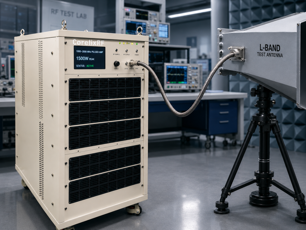
The 1000-2000 MHz window is relevant to L-band RF systems, communication test platforms, RF chain validation and pulsed system development. A buyer should identify whether the amplifier will drive a test load, antenna path, front-end subsystem, chamber path or production test fixture. Each use case changes mismatch exposure, measurement method and protection expectations.
For radar-related development, the amplifier may be part of a transmit-chain simulator, front-end validation bench or system-level pulsed RF rack. The inquiry should avoid vague terms such as “radar amplifier” without pulse detail. A stronger inquiry gives operating band, peak power, pulse width, duty cycle, repetition behavior, source level, output path and rack/control constraints.
Rack Format, Cooling and Weight Planning
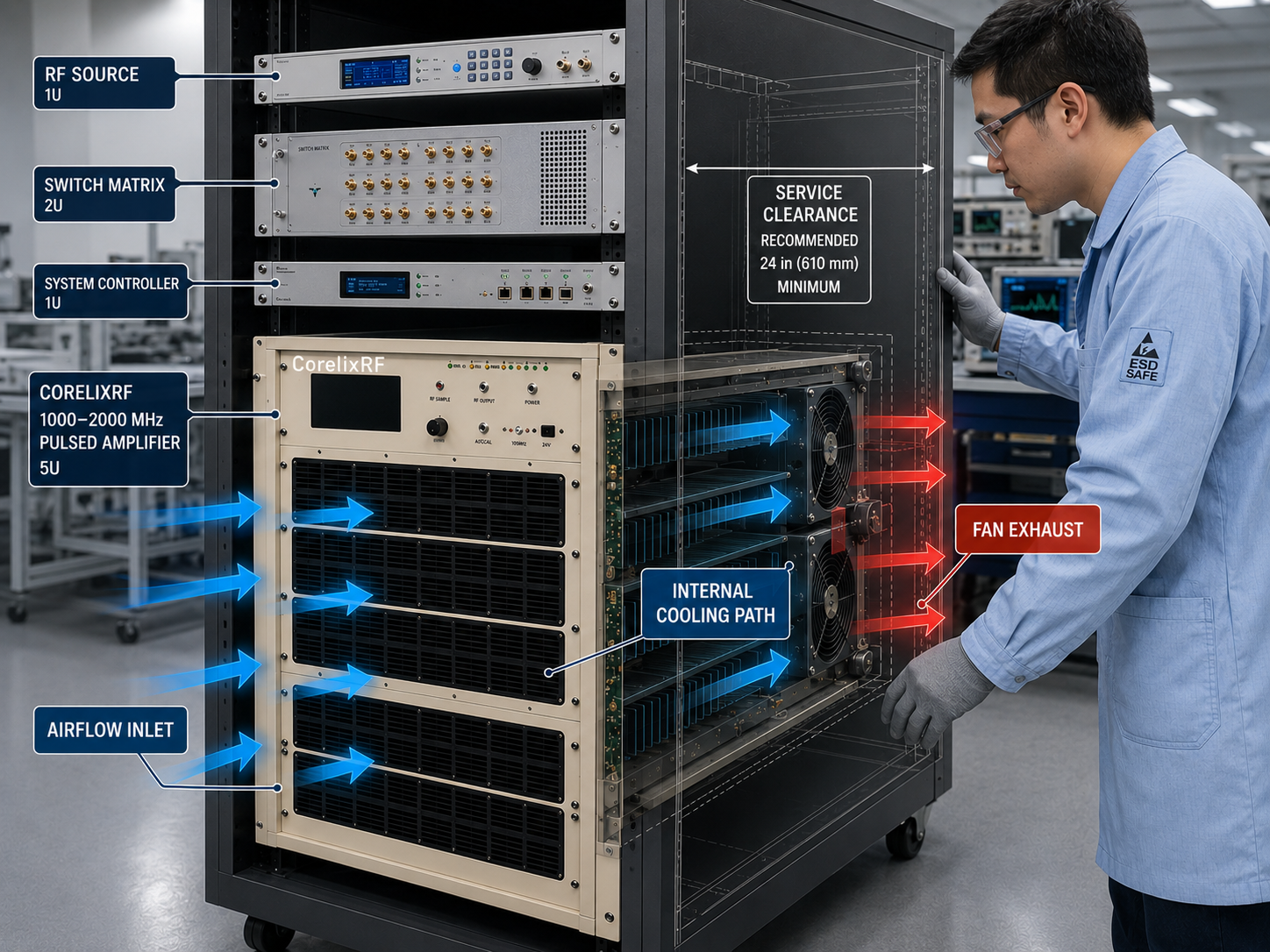
The CRF-PA-1000M2000M-1500W public table lists a 19-inch 5U rack structure and approximately 35 kg weight. That information matters before purchase. A 5U rack unit requires cabinet space, airflow planning, service clearance, safe handling and power distribution review. Integrators should confirm inlet temperature, airflow direction, duty-cycle thermal behavior and operating environment.
Cooling should be treated as a project condition, not a detail to solve after delivery. If the system cabinet already contains sources, switches, loads, computers or other RF equipment, include that context in the RFQ. A compact bench demonstration does not replace full rack thermal planning for a pulsed L-band system.
Control Interface and Timing
CorelixRF lists RS485/LAN control for this representative model. That is useful for host-controlled test systems, but the final control plan still needs review. The buyer should define enable timing, interlock behavior, fault monitoring, remote operation, operator workflow and any safety requirements around high-power pulsed output.
Automated systems should also describe how the amplifier is sequenced with the RF source, pulse generator, switching network, measurement equipment and load protection. The control interface is not only a communication port; it is part of the system’s repeatability and risk management.
Protection and Load Review
High peak RF power increases the need to review load match, connector rating, cable assembly, coupler selection, dummy load capacity and antenna path. If the amplifier may see mismatch, switched loads or changing antennas, describe those conditions clearly. Ask what protection behavior, alarm outputs and recovery process can be reviewed for the selected configuration.
For procurement, request a datasheet, measured RF data, mechanical outline, control notes, pulse-condition confirmation and available factory test records. Those documents help the engineering team evaluate whether the public model class matches the actual project rather than only the headline wattage.
RFQ Checklist
Send frequency range, rated output target, pulse width, duty cycle, repetition pattern, input drive, gain requirement, output connector, load or antenna path, cooling environment, rack constraints, control interface, monitoring needs, quantity and project stage. If your application needs a different frequency window or pulse format, say that directly so CorelixRF can review a project-specific pulsed PA configuration.
FAQ
What pulse condition is publicly listed for CRF-PA-1000M2000M-1500W?
CorelixRF lists a 1-50 microsecond pulse condition at 5 percent duty cycle for the representative 1000-2000 MHz 1500 W platform.
Is this a CW amplifier?
No. It is presented as a pulsed RF amplifier platform. CW requirements should be reviewed through the appropriate standard RF power amplifier family.
What control interfaces are listed?
The public table lists RS485/LAN control for the representative CRF-PA-1000M2000M-1500W platform.
What should I confirm before quotation?
Confirm pulse width, duty cycle, peak power, load condition, rack format, cooling, control interface, documentation needs and application.