
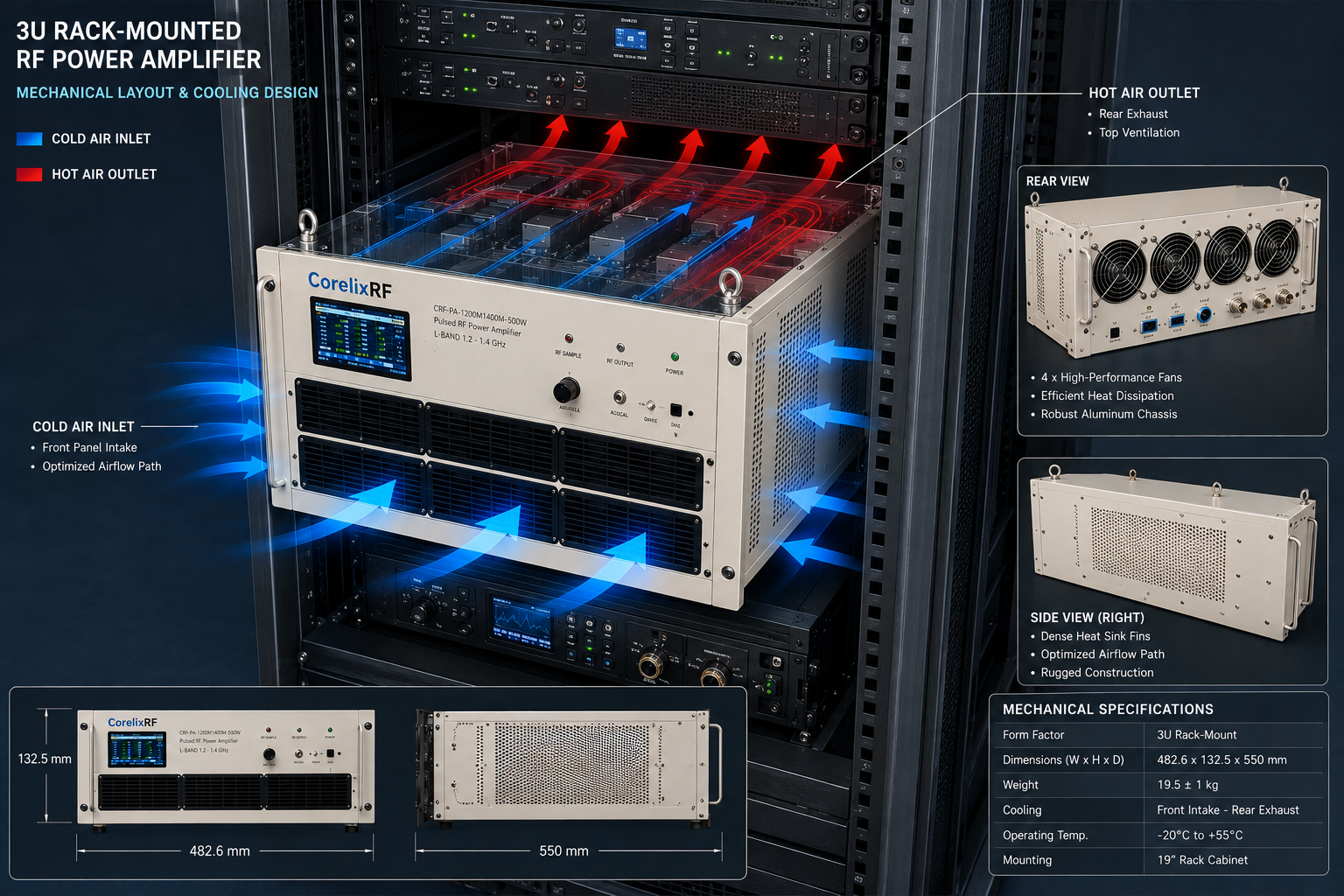
A 1200-1400 MHz 500W L-band pulsed amplifier is a more focused choice than a broad 1000-2000 MHz pulsed platform. It is relevant when the engineering team already knows the operating window and needs to concentrate RF performance, pulse behavior, rack integration and control around that narrower L-band range. The benefit is focus; the risk is assuming that frequency and wattage alone define the system.
CorelixRF lists CRF-PA-1200M1400M-500W as a representative narrowband L-band pulsed RF amplifier platform. Public information shows 1200-1400 MHz coverage, 500 W rated output, 57 dB gain, 50 microsecond pulse condition at 10 percent duty cycle, RS485/LAN control and a 19-inch 3U structure around 18 kg. These values give engineers a useful starting point for RF validation, communication verification and OEM rack-mounted integration.
Why Narrowband L-Band Review Can Be Better
A broad amplifier gives flexibility during early experimentation. A focused 1200-1400 MHz platform can be better when the target operating window is stable and the project needs a rack-ready pulsed output path. The buyer can focus the RFQ on pulse timing, gain, load match, cooling, control interface and validation data instead of paying attention to unnecessary frequency coverage.
The primary CorelixRF internal path is the pulsed RF amplifier page. If the same project may need broader 1000-2000 MHz coverage, compare the CRF-PA-1000M2000M-1500W platform from the same page. If the requirement changes into CW operation, the inquiry should move to an appropriate broadband RF power amplifier family instead.
Pulse Width and Duty Cycle Must Be Explicit
The public table lists a 50 microsecond pulse condition and 10 percent duty cycle for this model. That gives an important baseline, but the customer should still define the actual pulse plan. Repetition rate, burst structure, trigger method, source timing and enable sequence all affect whether a configuration is suitable.
Do not write an RFQ that only asks for “500 W L-band amplifier.” A better request states the pulse width, duty cycle, expected operating duration, input signal level, output path, load condition and control method. If your pulse condition differs from the public table, highlight that difference immediately.
Rack, Cooling and Mechanical Planning
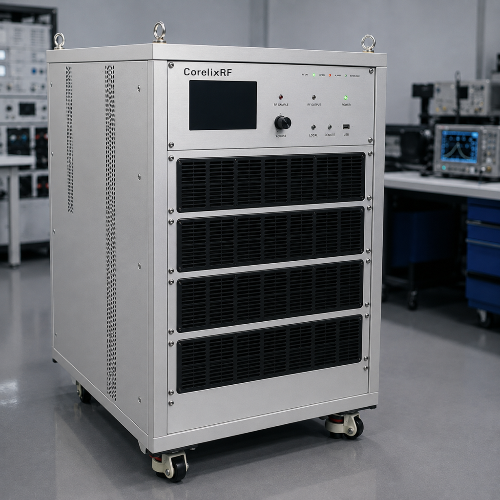
A 19-inch 3U, 18 kg rack unit is manageable in many RF labs, but it is still a system-level installation. Cabinet depth, rack rail support, airflow direction, inlet temperature, nearby heat sources and service clearance should be reviewed before ordering. If the amplifier will operate in a transportable rack or enclosed test cabinet, mechanical planning becomes even more important.
Cooling should be matched to the 10 percent duty-cycle use case or to the custom duty condition that the project requires. Share ambient temperature, airflow limits and expected run time. For system-level designs, also define DC power distribution and grounding assumptions.
Control Interface for Repeatable RF Validation
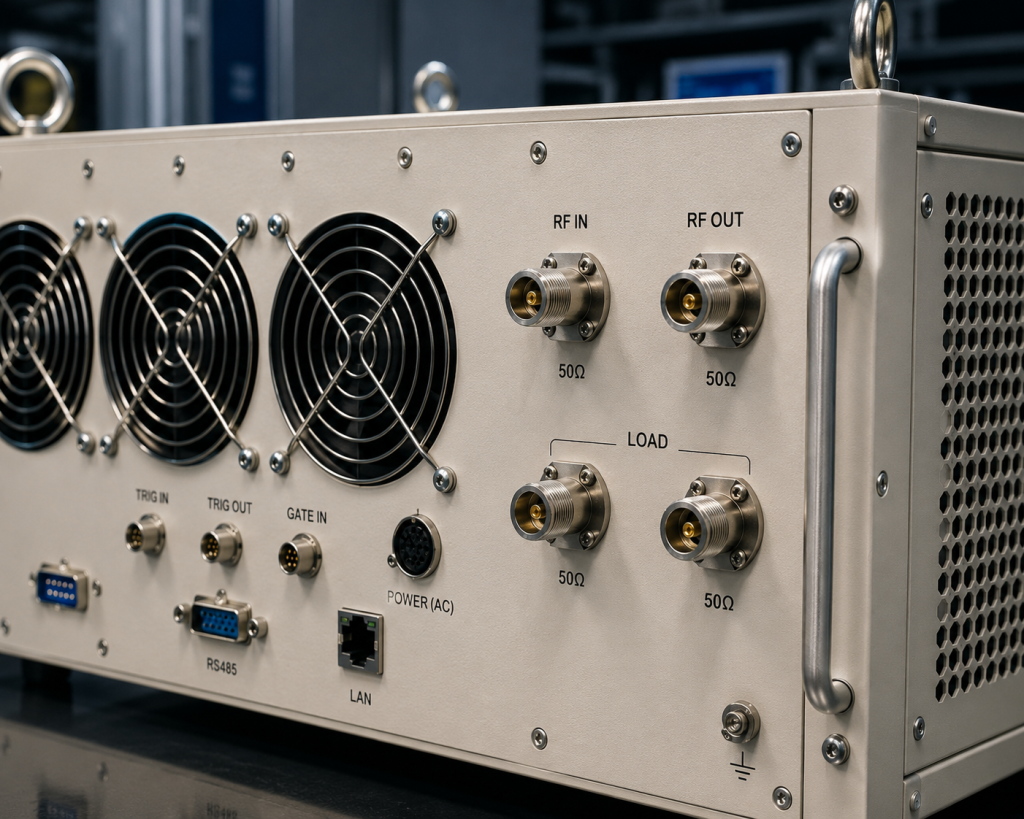
RS485/LAN control can support automated RF validation, but the integration plan should specify what the host system needs to read or command. Examples include enable/disable, fault status, interlock state, temperature or power monitoring, and reset behavior. Operator procedure should also be defined for fault recovery.
If the amplifier will be used in a repeatable qualification or production-style test bench, control and documentation requirements should be included in the first inquiry. That keeps the RF amplifier selection aligned with the software and test procedure, not just the RF chain.
Load Path and Protection Considerations
A 500 W pulsed amplifier can expose weak points in connectors, cables, couplers, loads and switching networks. Define whether the output will drive a matched load, antenna, fixture or front-end module. If there is a chance of mismatch, ask what protection behavior and test evidence can be reviewed for the selected configuration.
For communication verification, also describe modulation, source purity, output filtering and measurement method. For OEM integration, ask for mechanical outline, connector layout and control notes. For procurement, request a datasheet package and any available measured RF data.
RFQ Checklist
Send frequency range, output power target, pulse width, duty cycle, repetition behavior, input drive, load condition, RF connector path, rack constraints, cooling environment, control interface, monitoring expectations, documentation needs, quantity and project stage. When the standard 1200-1400 MHz path is close but not exact, ask CorelixRF to review a custom RF amplifier configuration.
FAQ
What is the listed frequency range for CRF-PA-1200M1400M-500W?
The public CorelixRF table lists 1200-1400 MHz.
What pulse condition is listed?
The representative model table lists 50 microseconds at 10 percent duty cycle.
What rack format is shown?
CorelixRF lists a 19-inch 3U structure with approximately 18 kg weight.
Is this model useful for RF validation?
Yes, it can be reviewed for communication verification, RF validation and OEM rack-mounted integration when the pulse and load conditions match the project.