
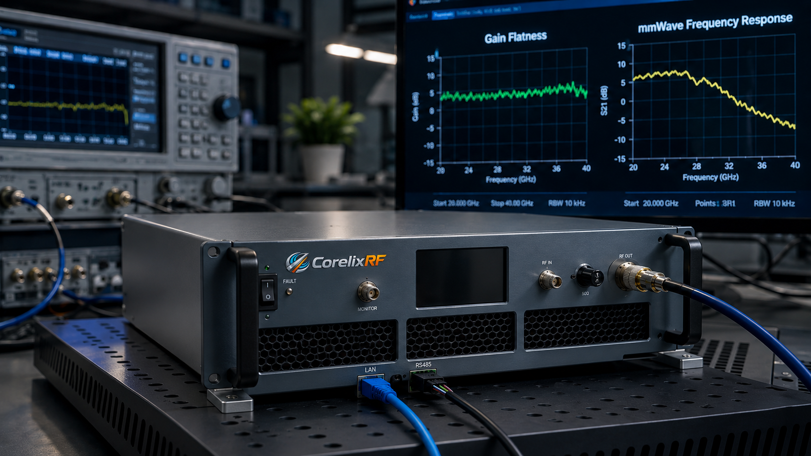
An 18-40 GHz mmWave RF power amplifier is usually purchased for a serious test or integration problem, not a casual bench upgrade. At K-band and Ka-band frequencies, every part of the RF path affects delivered power: connector transition, waveguide selection, rack format, cooling, cable and adapter loss, gain flatness, control interface and measurement setup. A buyer who only asks for frequency and wattage may receive a quotation, but not enough information to know whether the amplifier fits the real system.
CorelixRF lists the CRF-PA-18000M40000M series as the baseline full-band 18-40 GHz platform family. Public standard classes include 5 W, 20 W, 40 W and 70 W. The page also describes 2.92 mm input, 2.92 mm or WRD180 output depending on power class, 19-inch 3U, 4U or 8U rack formats, and RS485, LAN or GPIB control options. For RF test platforms and system integration, the CRF-PA-18000M40000M-40W is a practical discussion point because it sits in the mid/high standard class without moving directly to the largest 70 W configuration.
Start With the Real Operating Band
Full 18-40 GHz coverage is valuable when the test plan spans a broad microwave window. It is not always the best answer when the project only needs a focused band such as 18-26.5 GHz or a narrower Ka-band section. Before requesting a price, define whether power is needed across the entire band or only inside a specific test window. That decision changes connector path, rack height, cooling and measurement expectations.
The most direct CorelixRF internal page for this requirement is the 18-40 GHz RF power amplifier product page. If the project does not require full mmWave coverage and stops at 18 GHz, compare the 6-18 GHz RF amplifier family. If the requirement reaches beyond 40 GHz, review the millimeter-wave amplifier path instead.
Define the Output Interface Before the Rack Layout
At 18-40 GHz, the RF output interface is not a small purchasing detail. CorelixRF lists 2.92 mm-F for lower-power configurations and WRD180 for higher-power paths. The final choice should be reviewed against the test instrument, waveguide transition, load, antenna path, chamber feedthrough and rack layout. Adapter stacks can add loss and uncertainty, so connector and waveguide planning should happen before the mechanical drawing is locked.
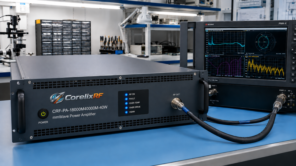
For a CRF-PA-18000M40000M-40W review, ask whether WRD180 output is the intended path and what rack format is expected. The published page associates the 40 W class with a 19-inch 4U configuration. That helps integrators reserve cabinet space, airflow clearance and service access early.
Cooling and Measurement Setup Are Part of the Specification
A mmWave amplifier can perform correctly on a factory test stand and still disappoint in the field if the customer’s installation loses too much power before the DUT. Cable loss, adapter loss, waveguide transition loss, load condition and measurement reference plane should be included in the RFQ. If the amplifier is part of an automated test system, define where power will be measured and how calibration will be maintained.
Cooling is equally important. Rack height, airflow direction, inlet temperature, duty cycle and expected run time all influence the final recommendation. For a custom RF amplifier review, include any cabinet airflow limits or noise restrictions. Do not wait until procurement has selected a model to discover that the system cabinet cannot move enough air.
Control Interface and Automation Needs
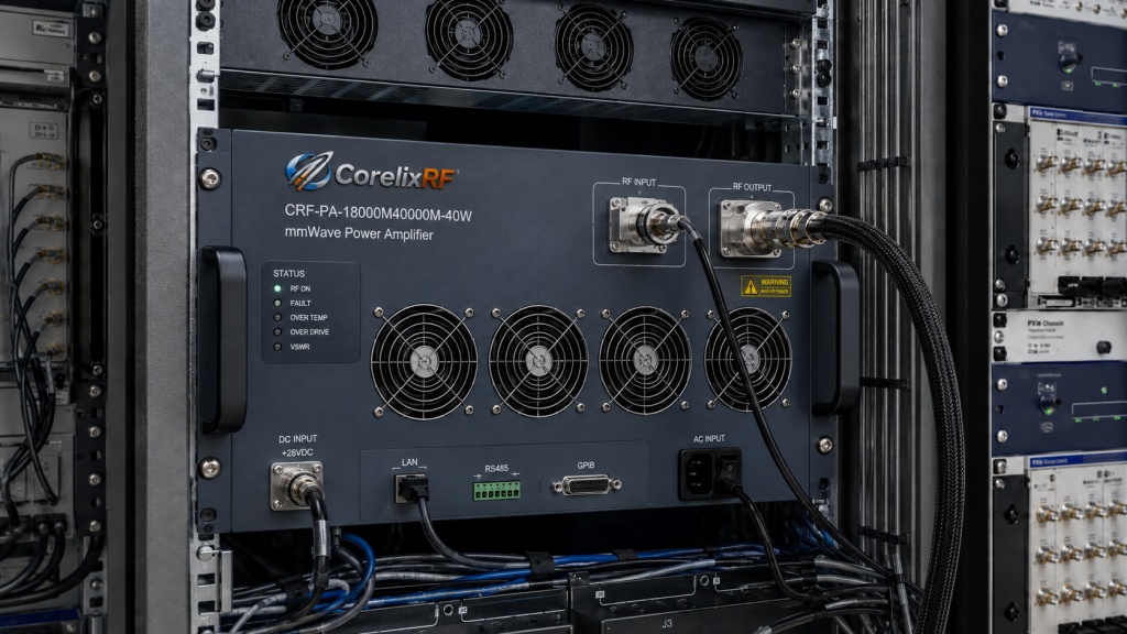
CorelixRF lists RS485, LAN and GPIB options for the 18-40 GHz family. The correct interface depends on the system workflow. Manual lab use may only need local operation and basic monitoring. Automated test equipment may require remote enable, fault reporting, interlock behavior and repeatable command timing. Production systems may need documentation and acceptance procedures.
A good RFQ should state the preferred control interface and whether the amplifier must integrate with existing software. If multiple racks are involved, also describe address management, operator safety behavior and expected fault recovery. These details make the request more actionable than a generic quote for a “40 W Ka-band amplifier.”
What to Request From CorelixRF
Ask for the model datasheet, measured output behavior, gain flatness reference, connector or waveguide configuration, rack outline, cooling requirement, control interface notes and available factory test documentation. If the project is still exploratory, ask for a data review before committing to a final power class.
For K/Ka-band work, the strongest RFQ package includes frequency window, target power at the load, waveform or CW mode, duty cycle, input drive, output interface, measurement setup, rack constraints, cooling environment, control interface, quantity and project stage. CorelixRF can then confirm whether the CRF-PA-18000M40000M-40W, another standard class or a focused-band custom configuration is the right path.
FAQ
What standard power classes are listed for 18-40 GHz amplifiers?
CorelixRF publicly lists 5 W, 20 W, 40 W and 70 W standard model classes for the CRF-PA-18000M40000M series.
Is WRD180 output always required?
No. Output path depends on power class and configuration. Lower-power models may use 2.92 mm output, while higher-power paths may use WRD180.
What should be included in an 18-40 GHz amplifier RFQ?
Include frequency range, output power target, input level, connector or waveguide path, control interface, rack size, cooling condition, application and project stage.
Can CorelixRF review focused-band higher-power options?
Yes. The public page notes that higher-power options may be reviewed for focused mmWave frequency windows when full 18-40 GHz coverage is not required.