
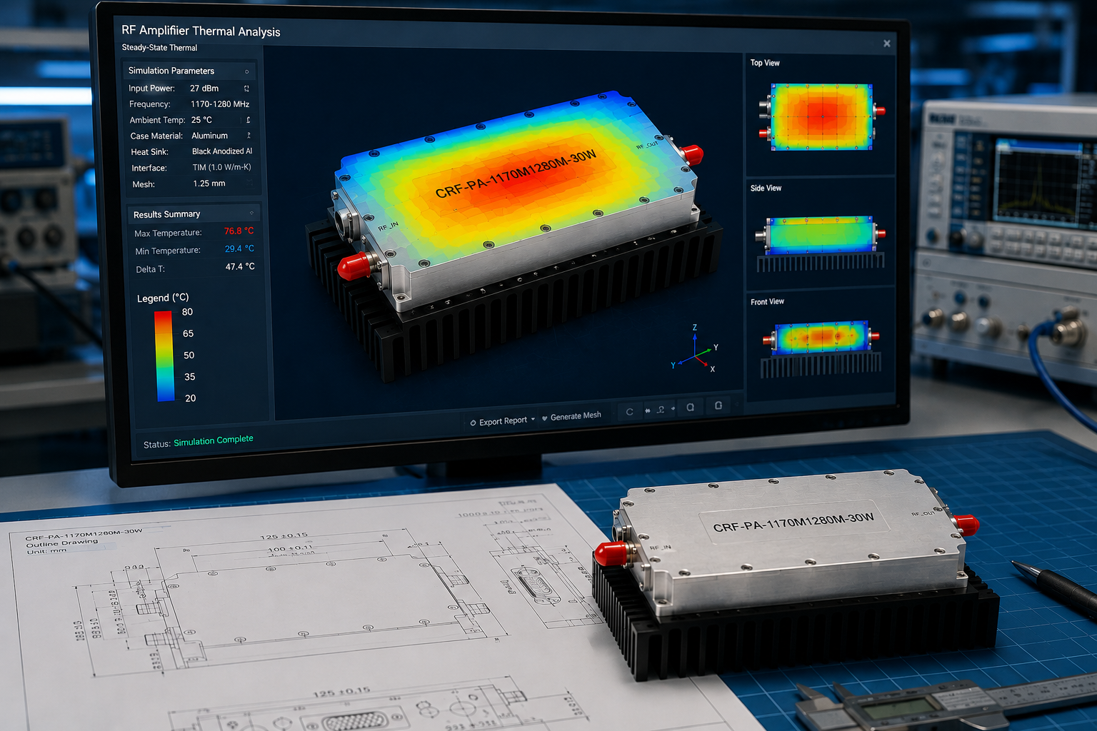
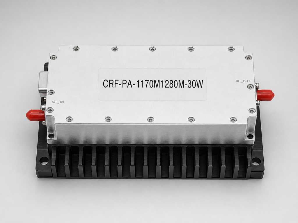
Review record: this note treats the CorelixRF CRF-PA-1170M1280M-30W as a design-review item for an L-band RF chain, not as a simple catalog purchase. The amplifier covers 1170-1280 MHz and delivers 30 W rated CW output power from a compact GaN SSPA module. That makes it relevant to GNSS-adjacent test benches, narrowband communication validation, and project-specific RF source integration where the band is already known and the team wants a focused RF power amplifier rather than a wideband rack unit.
Decision Context for the 1170-1280 MHz Narrowband RF Amplifier
The main decision is whether a 1170-1280 MHz narrowband RF amplifier should be specified as a standard gain and power block or as part of a source-integrated assembly. The datasheet lists an M version without internal VCO and a V version with an internal VCO source, 10 Hz stepping, 920-1300 MHz frequency adjustment range, and 50-380 MHz bandwidth adjustment range. If the system already has a disciplined RF source, the M version may be the cleaner path. If the system needs a source option, the V version changes the control and acceptance plan.
Inputs Accepted by the Review Board
- Frequency range: 1170 MHz to 1280 MHz.
- Rated output power: 30 W CW, with 25 W minimum output noted in the electrical table.
- Gain: 41 dB minimum, 43 dB typical, 45 dB maximum.
- Supply: +28 VDC nominal, with a 24-32 V operating range.
- Current: 3.2 A typical and 4 A maximum.
- Mechanical format: 125 x 59 x 21.5 mm, approximately 0.5 kg.
These numbers make the CRF-PA-1170M1280M-30W a compact UHF and L-band amplifier candidate. The small format is useful, but it also transfers responsibility to the integrator. The module needs a suitable heat sink, a stable supply, a defined input level, and a load path that will not turn a narrowband test into a mismatch event.
Risk Register
Thermal risk: the cooling method is external heat sink. The datasheet lists operation from -40 deg C to +60 deg C, shutdown above 80 deg C +/-5 deg C, and auto recovery below 70 deg C +/-5 deg C. The protection is useful, but the design should not depend on repeated thermal shutdown. Record heat-sink material, mounting pressure, airflow, and expected enclosure temperature before release.
Control risk: PA enable and disable time is listed up to 100 microseconds, and the control connector is D-Sub 9-pin female. If the host software turns on RF drive before the PA state is known, the measured output may be unstable. A startup sequence should confirm DC supply, cooling, RF source disable, PA enable, and then controlled RF drive.
Fit risk: the model uses SMA-KFD46 RF connectors. That choice needs to be checked against the source, coupler, load, and enclosure. If adapters are needed, the team should document them in the acceptance setup. At L-band, cable and adapter losses are manageable, but they still affect the difference between amplifier output and delivered power at the fixture.
Review Recommendation
Use this model when the requirement is concentrated inside 1170-1280 MHz and the project values a compact 30 W GaN SSPA stage. If the same bench must cover many adjacent bands, compare the requirement with CorelixRF’s 300-2700 MHz RF amplifier family before final selection. If the requirement changes connector, source, control, or thermal assumptions, move the inquiry into a custom RF amplifier review.
Release Conditions
The design should be released only after the team has recorded the selected M or V configuration, expected input drive, output target, duty cycle, heat-sink drawing, supply limit, load condition, and control timing. A short release sheet prevents the amplifier from being treated as an interchangeable part after engineering has already made narrowband assumptions.
Board Notes on Documentation and Handoff
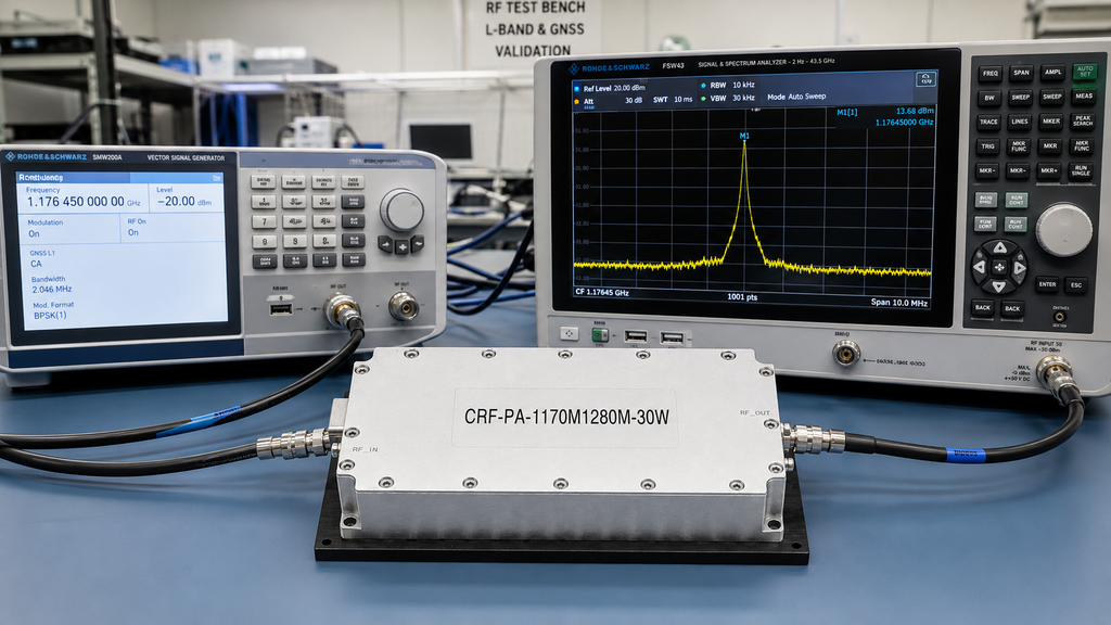
The review board should require a compact handoff file before the amplifier enters a program build. That file should include the model number, version choice, frequency plan, input source level, expected output target, heat-sink drawing, DC current limit, PA enable logic, and the intended 50 ohm load or antenna path. This is not paperwork for its own sake. It prevents later teams from changing the source, fixture, or cooling path without realizing that the original output result depended on those assumptions.
The handoff file should also state whether the amplifier is being used as a validation tool, a subsystem power stage, or a project-specific source-related module. Those three uses can require different acceptance evidence. A validation tool may need repeatable measured output across several test points. A subsystem power stage may need mechanical drawings and thermal review. A source-related module may need control commands and VCO behavior documented before software integration begins.
A useful final review question is whether the 30 W class leaves enough margin after expected cable, switch, filter, and fixture losses. If the delivered power target is defined at a device under test rather than at the amplifier output connector, those losses should be estimated before the model is approved. The review should also record whether continuous operation or intermittent test operation is expected, because that changes how aggressively the heat sink must be validated.
FAQ
Where does this amplifier fit in an L-band chain?
It fits where the system needs a focused 1170-1280 MHz power stage with compact GaN SSPA packaging.
What output power is listed?
The CRF-PA-1170M1280M-30W is listed for 30 W rated CW output power.
Does it require a heat sink?
Yes. The datasheet identifies external heat-sink cooling.
When should a custom review be requested?
Request a custom review if source integration, connector layout, monitoring, or thermal packaging differs from the standard module assumption.