
Handover Notebook
Bench condition: W-band test setup prepared for the next operator.
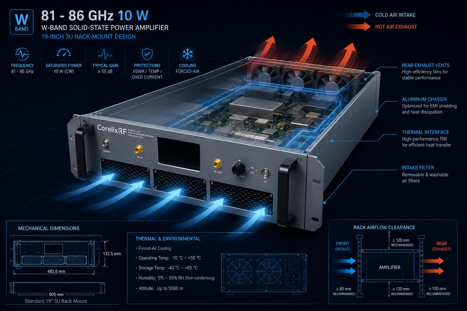
Amplifier under handover: CRF-PA-81G86G-10W, listed locally as a GaN SSPA covering 81 GHz to 86 GHz with 10 W rated output power, 40 dB minimum small-signal gain, WR10 input and output, forced-air 19-inch 3U configuration, temperature and current monitoring, alarm protection, and project-ready control interfaces.
This article is a field handover notebook. It is not a checklist, memo, or SOP. The goal is to preserve the physical and measurement context around a W-band mmWave power amplifier so the next engineer can reproduce the setup without guessing.
Note 1: What Was Connected
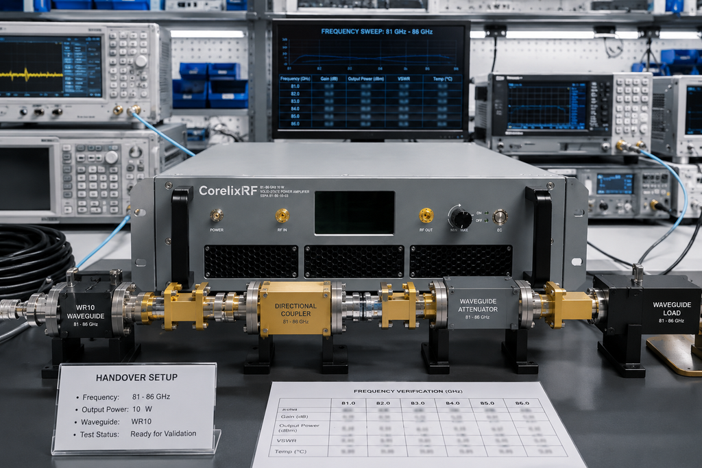
Record the WR10 path exactly: source transition, input waveguide or transition, amplifier input, amplifier output, output waveguide, coupler if used, load, measurement receiver, and any calibration hardware. At 81 GHz to 86 GHz, a small mechanical change can alter repeatability. The handover should name the hardware that was actually used, not merely the hardware that appears on a clean block diagram.
Note 2: What Was Limited
The next operator needs the source limit, starting drive level, gain condition, low-power verification step, and alarm response. With 40 dB minimum gain, safe operation cannot depend on memory. Write the source state and enable sequence into the handover so a later run begins from the same controlled condition.
Note 3: What Was Cooled
Forced-air 19-inch 3U hardware needs airflow direction, rack clearance, and nearby heat-source notes. If the amplifier ran for an acceptance period, include run duration, ambient condition, diagnostic readings if available, and whether any alarm appeared. A mmWave handover without thermal context is only half a record.
Note 4: What Was Measured
Save frequency points, measured output, output reference plane, source level, waveguide path, load identity, instrument model, calibration status if known, and deviations. CorelixRF’s high-frequency capability page reinforces the right review dimensions: frequency, power, interface, cooling, control, and validation evidence.
Note 5: What Changed
If an adapter, bend, load, coupler, transition, or calibration item changes, create a new handover note. At lower frequencies, informal adapter swaps may sometimes go unnoticed. At W-band, that habit can make an otherwise careful measurement impossible to compare.
Note 6: What the Next Shift Should Not Assume
Do not assume the visible waveguide path is the accepted path unless the handover says so. Do not assume a measurement is comparable after a transition or load has been swapped. Do not assume the rack airflow is acceptable because the amplifier powered on. Do not assume that source drive is safe because a previous run passed. At 81 GHz to 86 GHz, handover quality is part of measurement quality.
Notebook Entry Example
A useful entry might read: frequency points reviewed, WR10 path unchanged, load identity confirmed, source limit recorded, low-power verification completed, output readings saved, no alarm observed, airflow path clear, and next operator warned not to change the coupler without creating a new baseline. That kind of note is short enough to use and specific enough to protect the data.
RFQ Carryover
If the handover reveals unresolved items, carry them into the RFQ. Examples include a different WR10 hardware set, longer run time, additional monitoring, a special rack layout, or a measured-data format required by the customer. The handover should not hide these items as lab trivia; they are the exact details that decide whether a standard configuration is enough.
Continuity Note
The next useful handover should begin from this one, not replace it with a fresh story. Keep the accepted waveguide path, source limit, cooling note, and measurement file location stable unless a change is intentional. If a new operator improves the setup, record the old condition, the new condition, and the reason. That small continuity habit makes W-band work less mysterious and much easier to audit later. It also keeps procurement notes aligned with laboratory evidence and engineering review decisions. If the chain changes twice, create a fresh baseline before quoting performance.
Handover Close
The CRF-PA-81G86G-10W should stay in the candidate path when the project needs 81 GHz to 86 GHz coverage, 10 W output class, WR10 interfaces, and a rack-level forced-air platform. If the project needs a different range, output class, waveguide path, control behavior, or acceptance package, use RF integration context and send the requirement through Contact CorelixRF. The broader CorelixRF site can route adjacent RF platform questions.
FAQ
What frequency range is listed for CRF-PA-81G86G-10W?
The local CorelixRF specification evidence lists 81 GHz to 86 GHz.
What output power is listed?
The local datasheet lists 10 W. The usable condition should still be reviewed against waveform, reference plane, load, thermal boundary, and acceptance method.
What should be included in the RFQ?
Include frequency points, waveform, source level, output reference plane, load condition, connector path, cooling boundary, control interface, alarm behavior, and requested test data.
Does this article claim stock, certification, or customer deployment?
No. It stays inside local product specifications and general engineering guidance.
What is the main integration caution?
The handover must preserve the exact WR10 path, source limit, cooling condition, and measurement reference plane.