
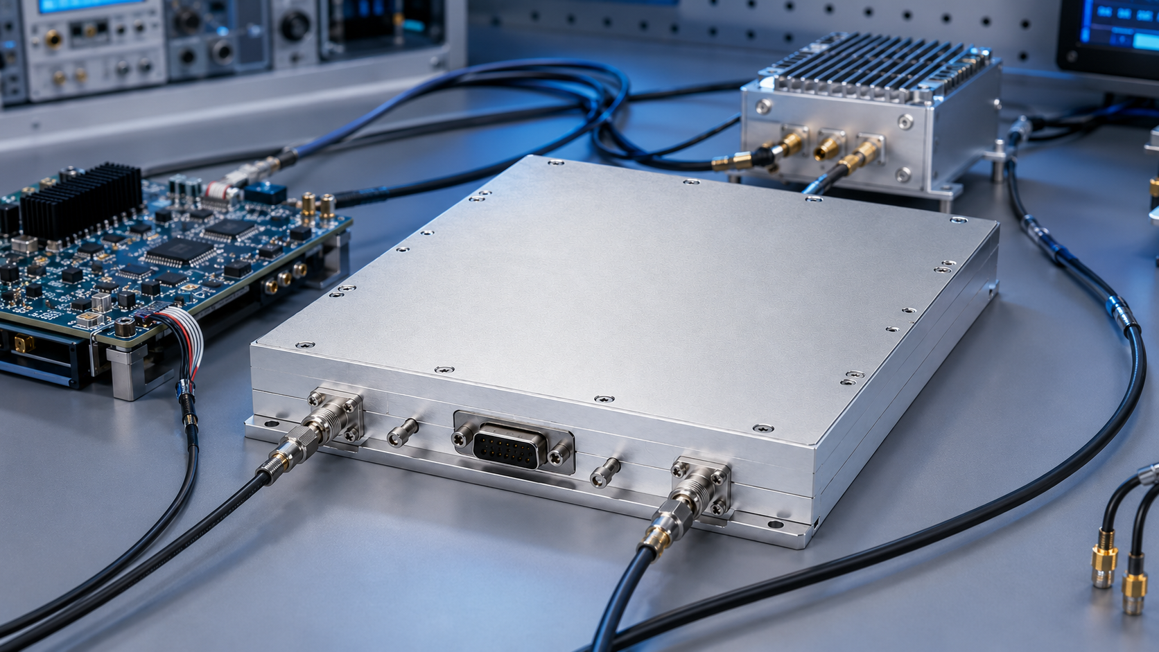
An embedded RF system needs a different kind of article than a rack-planning guide. The key question is not just which amplifier to buy, but how the amplifier fits into the source, controller, thermal plate, enclosure, enable logic, and protection model. For engineers searching narrowband RF amplifier, L-band RF amplifier, RF amplifier module, or RS485 RF amplifier, the architecture decisions are often more important than a long list of generic amplifier benefits.
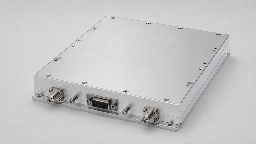
The CorelixRF CRF-PA-1560M1620M-150W is a GaN narrowband RF amplifier covering 1560 MHz to 1620 MHz with 150 W rated CW output power. The local datasheet lists third-generation GaN transistors, SMA-KFD46 RF connectors, a 200 x 158 x 25 mm form factor, 48 dB minimum gain, 50 dB typical gain, 52 dB maximum gain, gain adjustment, optional RS485 monitoring/control, PA enable/disable control, external heat-sink cooling, and over-temperature, VSWR, voltage, and current protection. It also identifies M and V configurations, with the V version including an internal VCO source and 10 Hz stepping.
Architecture Block 1: RF Source Strategy
The first architecture decision is whether the system already has a qualified RF source. If it does, the amplifier can be specified as an amplification stage. If not, the optional V version with internal VCO source may reduce subsystem complexity. That choice affects calibration, control software, test procedure, and spare-part strategy.
A narrowband RF amplifier should be specified with actual operating channels, not only the full 1560-1620 MHz range. If the system operates at fixed frequencies, state them. If it uses fine stepping, define tuning and verification expectations.
Architecture Block 2: Gain and Enable Control
The datasheet lists 48/50/52 dB minimum, typical, and maximum gain. That much gain requires a planned input level. Add input attenuation or source limits where needed. Define how gain adjustment is set during production, calibration, and field service.
PA enable/disable control should be part of the system state machine. A good design prevents the amplifier from enabling before the source, load, cooling, and controller are ready. This matters for any RF amplifier module that is embedded inside a larger product rather than used as an open bench device.
Architecture Block 3: RS485 Monitoring
Optional RS485 monitoring/control can simplify equipment integration. The system controller can read status, coordinate enable logic, and respond to alarms without requiring a front-panel operator. When requesting this option, state the preferred data points, update rate, alarm mapping, and reset behavior.
Do not treat RS485 as a checkbox. It should connect to a defined control workflow: initialization, normal operation, fault state, recovery, service mode, and acceptance testing.
Architecture Block 4: Thermal Interface
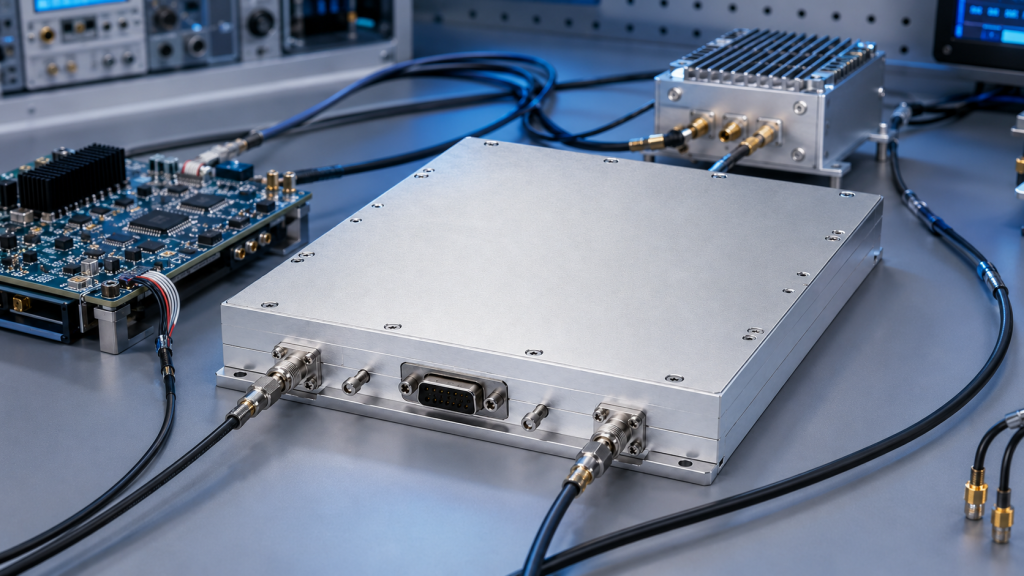
The 200 x 158 x 25 mm form factor and external heat-sink cooling create a compact integration opportunity, but they also make the mechanical team responsible for thermal performance. Define the heat sink, mounting interface, airflow, thermal material, ambient range, and installation orientation.
For a 150W GaN amplifier, thermal validation should be run inside the actual enclosure or a representative fixture. Record output power, current, temperature, and alarm state. If the enclosure is sealed or exposed to high ambient temperatures, discuss thermal limits early with CorelixRF.
Architecture Block 5: Protection and Fault Recovery
The source datasheet lists over-temperature, VSWR, voltage, and current protection. These features should be integrated into system logic. For example, VSWR or over-temperature alarm may disable PA enable, mute the source, log a fault, and require a controlled restart.
If the system has unusual environmental, control, or packaging requirements, CorelixRF’s custom RF amplifier process is the right path to discuss project-specific constraints. If the requirement broadens beyond 1560-1620 MHz, the broadband RF power amplifier portfolio may be more suitable.
Architecture Review Checklist
Before design freeze, confirm the source strategy, VCO requirement, operating channels, input drive level, gain adjustment method, RS485 requirement, PA enable logic, heat-sink design, airflow, connector access, protection response, acceptance test points, and service procedure. Also decide whether the amplifier is treated as a replaceable RF amplifier module or a fixed part of the enclosure.
This architecture-first approach keeps the amplifier from becoming a late-stage packaging problem.
FAQ
What focus keyword should this article use?
Use 1560-1620 MHz narrowband RF amplifier, supported by narrowband RF amplifier, L-band RF amplifier, 150W GaN amplifier, and RF amplifier module.
What output power is listed for this amplifier?
The local datasheet lists 150 W rated CW output power.
What control options are listed?
The datasheet lists gain adjustment, optional RS485 monitoring/control, and PA enable/disable control.
What protection functions are listed?
The source datasheet references over-temperature, VSWR, voltage, and current protection.
SEO and Integration Notes for This Architecture
The strongest search phrase is 1560-1620 MHz narrowband RF amplifier because it combines frequency range, product type, and buying intent. Supporting terms such as narrowband RF amplifier, L-band RF amplifier, 150W GaN amplifier, RF amplifier module, and RS485 RF amplifier should be used where they match the architecture discussion. This keeps the article useful for engineers while still giving search engines clear topical signals.
For integration, the most important decision is whether the amplifier will be treated as a controlled module or a simple RF gain block. If the system uses RS485, PA enable, VCO stepping, thermal alarms, and fault recovery, the amplifier belongs in the system architecture document. That is the right place to define startup sequence, control states, service access, thermal validation, and acceptance testing.