
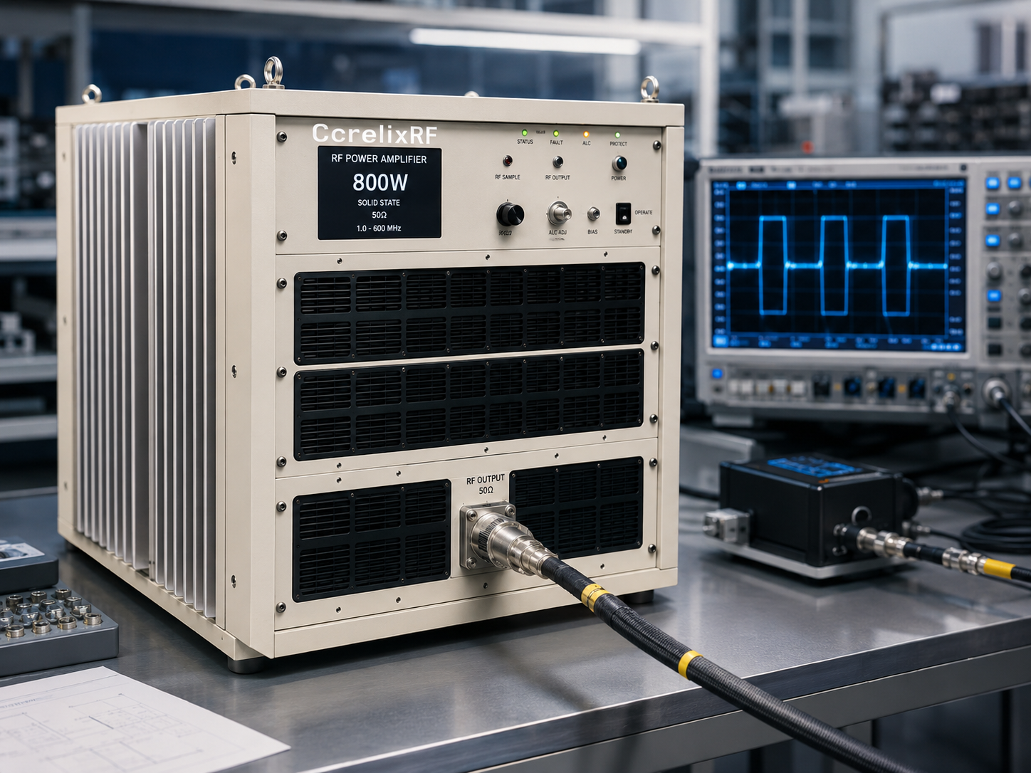
Many pulsed RF amplifier problems begin before the amplifier arrives. The RFQ says 800 W, the purchase order says 5.8-6.7 GHz, and the test team later discovers that pulse width, duty cycle, driver level, output hardware, or cooling was never defined clearly enough. This article uses a failure-analysis format so engineers can avoid those problems when specifying a high power RF amplifier for pulsed C-band work.
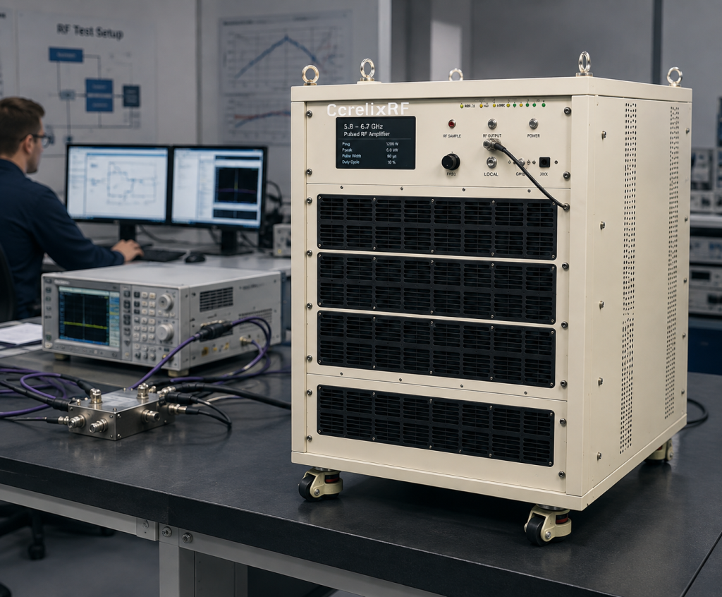
The CorelixRF CRF-PA-5800M6700M-800W is a GaN SSPA covering 5,800 MHz to 6,700 MHz with 800 W rated output power. The local datasheet lists N-Female input, 7/16-Female output, 62 dB minimum small-signal gain, -2 to +2 dB gain flatness, up to 20 dB gain control, air or water cooling, temperature/current diagnostics, alarm protection, and project-specific mechanical configuration. Those facts support SEO search terms such as 5.8-6.7 GHz pulsed RF amplifier, pulsed RF amplifier, 800W RF amplifier, and C-band pulsed amplifier.
Failure 1: The RFQ Mentions Peak Power but Not Pulse Conditions
An pulsed RF amplifier cannot be specified by peak power alone. Pulse width, pulse repetition frequency, duty cycle, burst length, test duration, and average power all affect thermal load and acceptance. If these are missing, supplier and buyer may both be technically correct while still expecting different operating behavior.
The fix is simple: write the waveform requirement. Include frequency points, peak output power, average power estimate, pulse width range, PRF, duty cycle, and whether the amplifier is driven by gated RF, pulsed input, or another control method.
Failure 2: The Driver Chain Cannot Support the Gain Plan
The datasheet lists 62 dB minimum small-signal gain and up to 20 dB gain control. That gives the integrator room to work, but only if the input chain is planned. A source, modulator, switch, cable set, attenuator, and pre-driver can all change available drive. Overdrive can damage test validity. Underdrive can make the amplifier look weak even when the amplifier is not the limiting device.
Treat the RF power amplifier as one block in a controlled chain. Calculate expected input level at each operating case and put limits into the procedure or software.
Failure 3: The Output Path Is Rated for Average Power, Not Peak Stress
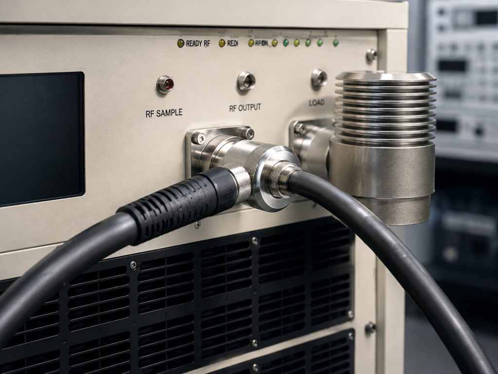
The CRF-PA-5800M6700M-800W lists a 7/16-Female output. The output cable, load, directional coupler, switch, and antenna feed should be selected for frequency, peak power, average power, and mismatch exposure. A test setup may survive a short demonstration and fail during a longer campaign if the output path was marginal.
Before applying drive, verify the load and any switch state. If the rack has removable fixtures, use interlocks or operator checks to prevent an unterminated high-power output path.
Failure 4: Cooling Was Chosen Too Late
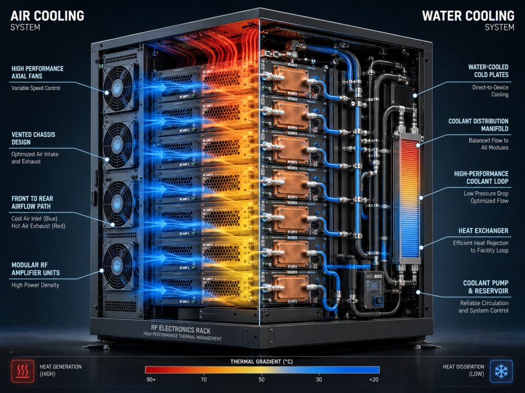
The datasheet lists air or water cooling. Cooling should be selected before the mechanical design is complete. Air cooling can be simpler, but it needs intake and exhaust space. Water cooling can support dense layouts, but it adds flow, plumbing, leak, and facility requirements.
For an 800W RF amplifier, validate thermal behavior with the actual pulse profile. Log temperature, current, output power, frequency, and alarm status. Do not rely on a short low-duty test if the final use is longer or more demanding.
Failure 5: Alarm Handling Is Not Written Into the System
Temperature/current diagnostics and alarm protection are useful only when the rack knows what to do with them. Define whether an alarm mutes the source, disables PA enable, opens an interlock, stops the sequence, logs data, or requires manual reset. Without this logic, protection becomes an after-the-fact indicator rather than part of the operating design.
If the project needs special timing, packaging, or control behavior, a custom RF amplifier review is better than forcing an unusual requirement into a generic purchase note.
A Better Specification Format
Use this RFQ structure: application, frequency range, fixed channels or sweep plan, peak power, average power, pulse width, PRF, duty cycle, input drive level, gain control, connector requirements, cooling method, rack or module constraints, diagnostics, alarm behavior, acceptance data, and load condition. If the project is actually CW rather than pulsed, review CW solid-state RF amplifier options instead. If the purpose is compliance or immunity testing, review the EMC RF amplifier category.
FAQ
What is the best focus keyword?
The best focus keyword is 5.8-6.7 GHz pulsed RF amplifier, supported by pulsed RF amplifier, 800W RF amplifier, high power RF amplifier, and GaN SSPA.
What output power is listed?
The local datasheet lists 800 W rated output power across 5.8 GHz to 6.7 GHz.
Why do pulsed RF amplifier tests fail?
Common causes include missing pulse conditions, unclear average power, weak driver planning, underrated output hardware, late cooling decisions, and undefined alarm handling.
What gain is listed for this amplifier?
The datasheet lists 62 dB minimum small-signal gain and up to 20 dB gain control.
SEO and Specification Notes for Pulsed Amplifier Buyers
For search visibility, the article should keep 5.8-6.7 GHz pulsed RF amplifier as the primary phrase and support it with pulsed RF amplifier, 800W RF amplifier, high power RF amplifier, C-band pulsed amplifier, and GaN SSPA. These keywords have strong commercial intent because they describe a buyer who already knows the band, power class, and operating mode. The content should use them to clarify requirements rather than repeat them as a list.
For the RFQ, ask CorelixRF to review pulse conditions together with cooling and output hardware. A pulsed amplifier can look easy to specify when only frequency and peak power are discussed, but the acceptance test depends on waveform timing, average power, thermal behavior, and the way alarms are handled during repeated bursts.