
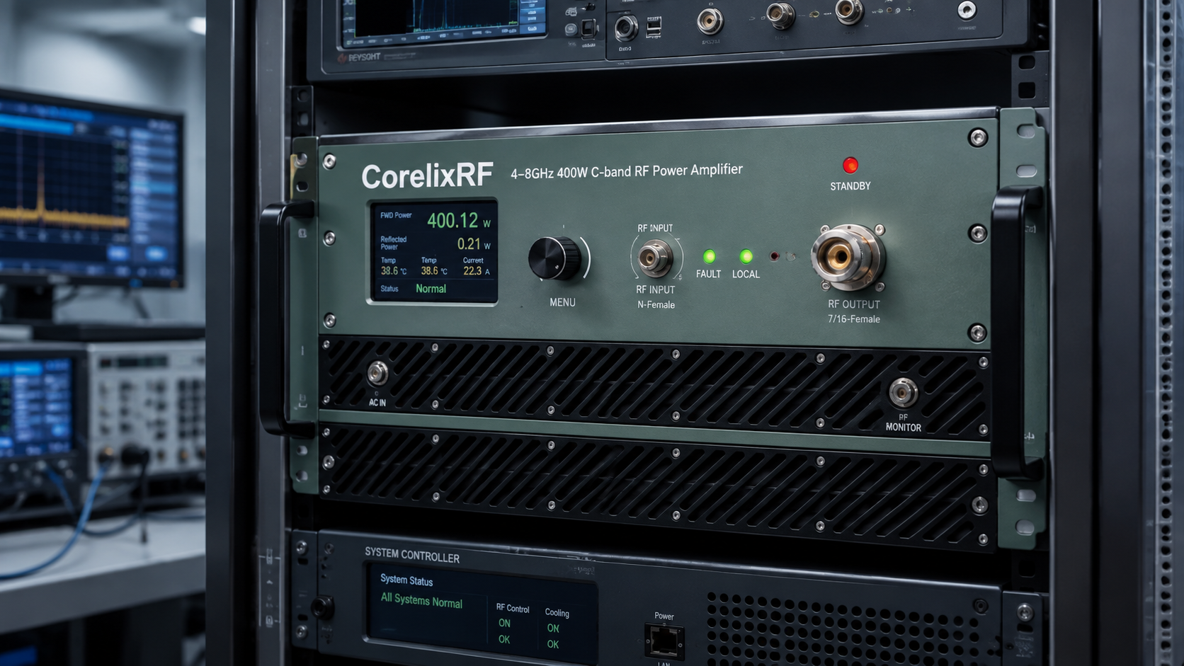
This application note explains how to plan a 4-8 GHz RF power amplifier rack for C-band test work. The goal is practical: take a high-power GaN amplifier, connect it to a source and load safely, preserve enough gain control for repeatable measurements, and leave operators with a rack that can be used without guessing.
The CorelixRF CRF-PA-4000M8000M-400W is the example platform. Its datasheet lists 4,000 MHz to 8,000 MHz coverage, 400 W rated output power, N-Female input, 7/16-Female output, 59 dB minimum small-signal gain, -4 to +4 dB gain flatness, air or water cooling, real-time temperature/current diagnostics, alarm protection, and project-specific mechanical configuration. These details support high-search engineering topics such as C-band RF amplifier, broadband RF amplifier, GaN power amplifier, and RF amplifier test rack.
Step 1: Draw the RF Chain
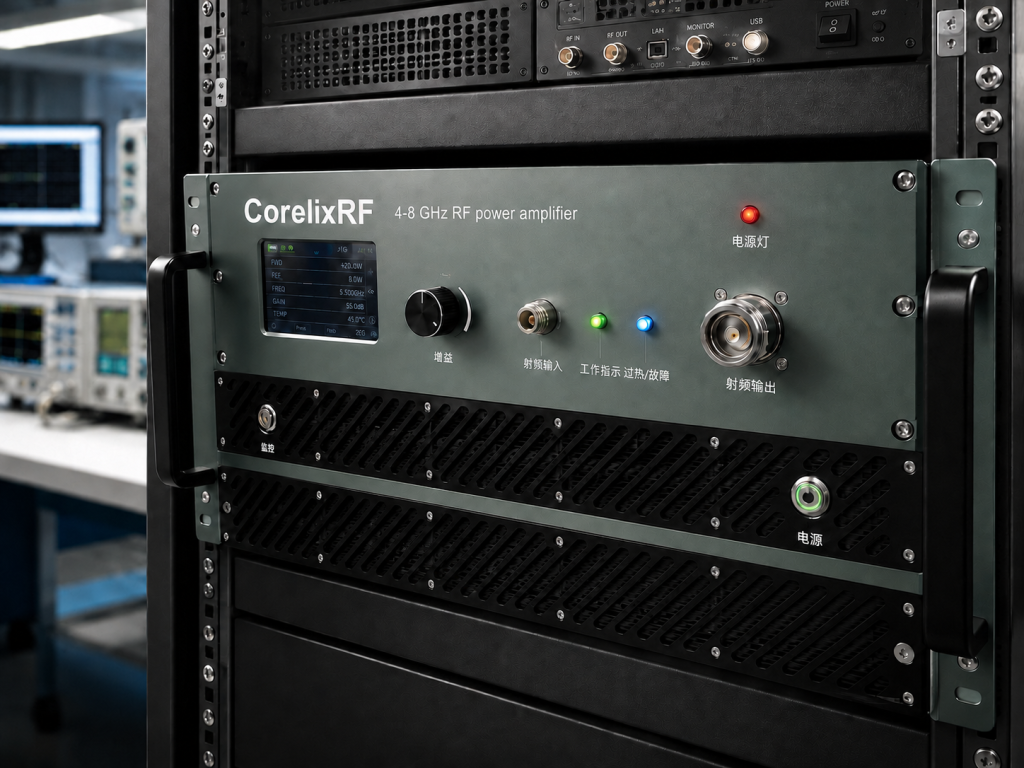
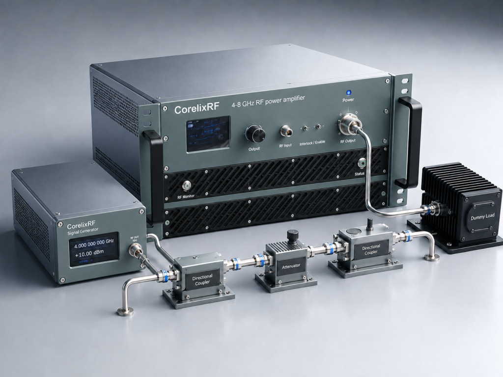
Start with the signal source, then add any pre-driver, attenuator, switch, coupler, amplifier input, amplifier output, load, antenna, or device under test. Mark each expected loss. This step prevents a common integration mistake: selecting a RF power amplifier by rated output power while forgetting that the driver chain cannot reach the required input level.
Because the CRF-PA-4000M8000M-400W provides 59 dB minimum gain, the rack may not need an aggressive pre-driver. It does need an input power limit. Add a fixed attenuator or software-controlled source limit if operator error could overdrive the amplifier.
Step 2: Choose the Output Hardware Around 400W
The datasheet lists a 7/16-Female output connector. Select the output jumper, directional coupler, load, switch, and antenna feed for 4-8 GHz operation and 400 W class power. Do not reuse a low-power C-band cable simply because the connector fits.
For a CW solid-state RF amplifier, the output path should be treated as part of the amplifier system. Label the cable set, define connector torque practice, and verify the load before enabling drive. If the rack includes a switch matrix, interlock the dangerous states.
Step 3: Decide Air or Water Cooling Before Packaging
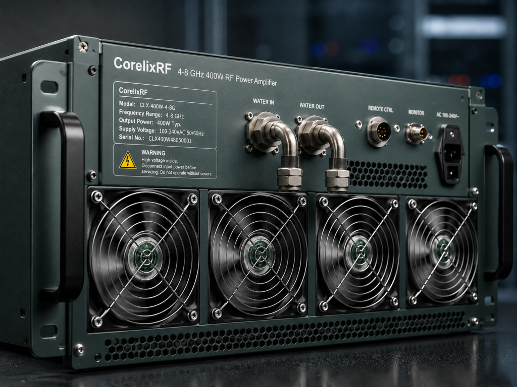
The source datasheet lists air or water cooling. Choose early, because the decision changes the rack. Air cooling requires intake space, exhaust clearance, filter access, and room airflow. Water cooling adds plumbing, flow checks, leak planning, and facility compatibility. Neither choice is automatically better; the correct option depends on duty cycle, ambient temperature, rack density, and maintenance expectations.
Run a thermal verification using representative frequency points and output levels. Record temperature, current, output power, and alarm state. This gives the test team a baseline for future troubleshooting.
Step 4: Build the Control Flow
A modern RF amplifier test rack should not depend on manual timing. Define startup, enable, level set, measurement, alarm response, and shutdown steps. If the project uses remote control, map amplifier diagnostics into the rack software. If it is a manual station, place the indicators where operators can act on them.
Real-time temperature and current diagnostics are useful because they help distinguish RF mismatch, thermal buildup, and drive-level problems. Alarm protection is not a replacement for interlocks, but it gives the rack another layer of visibility.
Step 5: Write the Acceptance Test
Acceptance should include frequency coverage, output power, gain behavior, gain flatness, cooling response, alarm reporting, and output-path verification. The test should identify the measurement reference plane. For a 4-8 GHz broadband RF amplifier, measure enough points to represent the band rather than relying on a single center-frequency check.
If the end use is communications validation, include waveform or modulation notes. If the end use is RF interference or EW system-level testing, include duty cycle and fixture conditions. If the rack is only for component characterization, define repeatability and calibration intervals.
Practical Rack Layout Notes
Put the amplifier where airflow is not blocked. Keep high-power output routing short and mechanically supported. Keep low-level input lines away from hot exhaust and high-current wiring. Place the coupler and power sensor where operators can verify output without disturbing the main path.
If the mechanical requirement differs from a normal rack, CorelixRF’s custom RF amplifier path should be discussed before the hardware layout is frozen. For lower-frequency immunity work, the EMC RF amplifier category may fit better than a C-band rack.
FAQ
What keyword should this article target?
The strongest target is 4-8 GHz RF power amplifier, supported by C-band RF amplifier, 400W RF power amplifier, broadband RF amplifier, and RF amplifier test rack.
What output power is listed for the CRF-PA-4000M8000M-400W?
The local datasheet lists 400 W rated output power across 4,000 MHz to 8,000 MHz.
What output connector is listed?
The datasheet lists a 7/16-Female output connector.
Should the rack use air or water cooling?
The datasheet lists air or water cooling. The final choice should be based on duty cycle, rack density, facility constraints, and maintenance expectations.
SEO and Documentation Notes for the Rack File
For the WordPress draft, the strongest keyword placement should use 4-8 GHz RF power amplifier in the title, first paragraph, one H2, and the FAQ. Secondary terms such as C-band RF amplifier, broadband RF amplifier, GaN power amplifier, and RF amplifier test rack should appear naturally where they describe real engineering decisions. The article should not repeat the same anchor text several times; it should use each term once in a useful context.
The documentation package should also include a block diagram, cable list, calibration reference plane, cooling decision, and alarm-response table. Even when the amplifier is purchased as a standard product, these supporting details make the rack easier to review, quote, build, and troubleshoot. For a high-power C-band platform, good documentation is part of the RF design.