
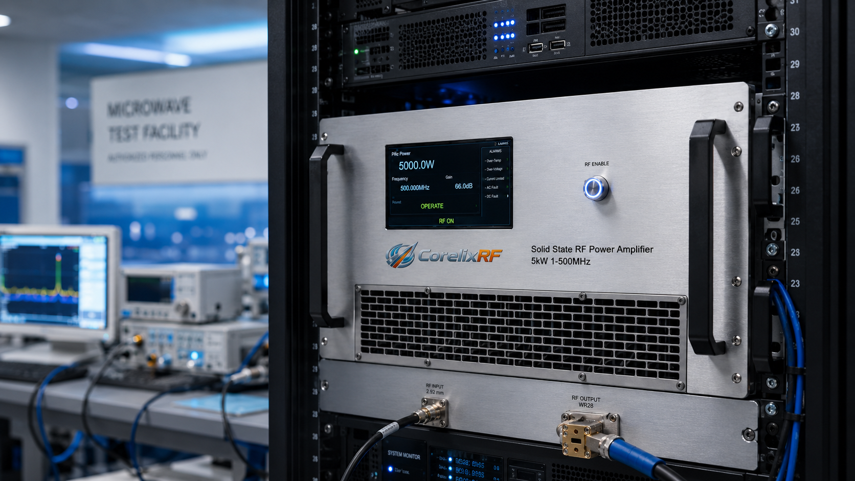
fWhen engineers search for a 26.5-40 GHz RF power amplifier, the buying decision usually starts with a simple phrase: Ka-band power, solid-state reliability, and enough output for the test range. The actual procurement decision is more detailed. At 40 GHz, the amplifier has to fit the signal chain, the waveguide plan, the rack layout, the cooling path, the control system, and the acceptance test method. A high-search keyword such as microwave power amplifier is useful for discovery, but the final RFQ should still be based on measurable electrical and mechanical requirements.
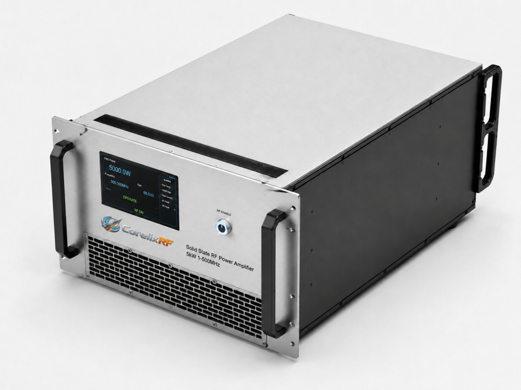
The CorelixRF CRF-PA-26500M40000M-120W is a GaN solid state power amplifier covering 26.5 GHz to 40 GHz with 120 W rated output power. The local datasheet lists a 19-inch 5U rack-mount configuration, 2.92 mm female input, WR28 output, 51 dB minimum small-signal gain, forced-air cooling, temperature/current diagnostics, and alarm protection. That combination makes it relevant for Ka-band test and measurement instrumentation, communication system validation, RF interference or EW system-level testing, and aerospace control test platforms.
Buyer Requirement 1: Confirm the Real Output Reference Plane
The phrase RF power amplifier often hides a basic problem: different teams measure output at different places. One engineer may mean amplifier output. Another may mean the power after a coupler, waveguide run, switch matrix, or antenna fixture. Before comparing suppliers, define the reference plane and the required output power at that point.
For this 120W Ka-band amplifier, the amplifier rating is only one part of the link budget. Loss from coaxial cables, waveguide transitions, couplers, adapters, and fixtures can quickly consume several dB. A useful RFQ should include source power, estimated path loss, required delivered power, frequency points, and whether the system will run fixed-frequency tests or swept testing across the full 26.5-40 GHz range.
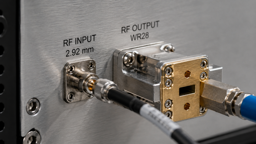
Buyer Requirement 2: Treat 2.92 mm and WR28 as System Decisions
The CRF-PA-26500M40000M-120W uses a 2.92 mm female input and WR28 output. These interfaces should be selected into the rack drawings, calibration kit, spare adapter list, and operator procedure. At Ka-band, casual adapter chains can create avoidable insertion loss, poor repeatability, and mechanical strain.
When comparing a broadband RF power amplifier, ask for interface drawings and output-path recommendations before the rack is built. The correct time to solve waveguide routing is during procurement, not during final acceptance when the amplifier is already installed.
Buyer Requirement 3: Match Gain and Drive Level
The datasheet lists 51 dB minimum small-signal gain and a gain control range up to 15 dB. This is useful for systems driven by moderate-level microwave sources, but it does not remove the need for an input drive calculation. Source power, preamplifier gain, cable loss, attenuator range, and software limits should be reviewed together.
A GaN SSPA used in a test rack should have a controlled startup sequence. Define maximum input drive, normal drive level, gain-control settings, and shutdown behavior. If the system is automated, the software should prevent overdrive and log the conditions that existed when an alarm occurred.
Buyer Requirement 4: Verify Cooling Before Final Rack Layout
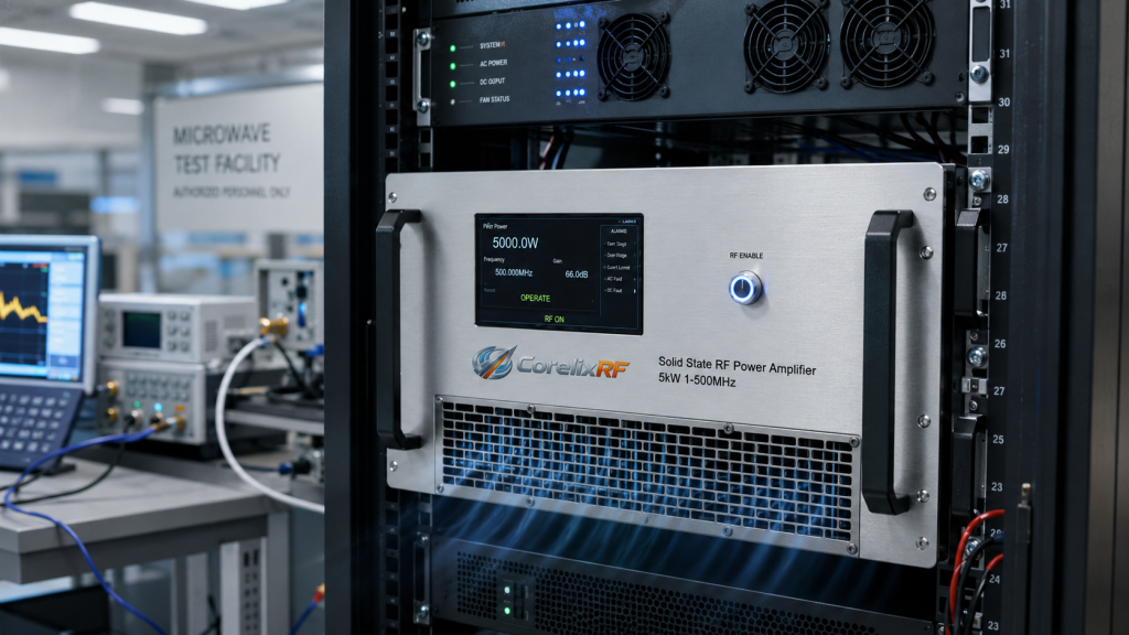
Forced-air cooling in a 5U rack format is practical, but the rack still has to move heat correctly. Check intake clearance, exhaust path, neighboring heat sources, filter access, and room airflow. For long test campaigns, the acceptance procedure should log temperature, current, frequency, drive level, and output power.
The right question is not whether the amplifier has a fan. The right question is whether the complete rack can keep the microwave power amplifier within its intended operating environment under the actual test profile.
Buyer Requirement 5: Ask for Diagnostics and Alarm Behavior
Temperature/current diagnostics and alarm protection are listed in the datasheet. For procurement, ask how alarms are reported, whether remote monitoring is available for the project, how the amplifier recovers after a fault, and what load conditions should be avoided. This matters when the amplifier will be used by multiple operators or integrated into an automated station.
If a standard rack does not match the control or mechanical requirement, start a custom RF amplifier discussion early. Customization should be planned around the RF chain, not added after the enclosure and software are already fixed.
RFQ Summary for Procurement Teams
Include these items in the RFQ: 26.5-40 GHz frequency range, 120 W rated output target, power reference plane, input drive range, connector and waveguide requirements, rack height, airflow direction, gain control, alarm reporting, acceptance test points, and expected operating profile. If the application is closer to lower-frequency immunity testing, review CorelixRF’s EMC RF amplifier platforms instead.
FAQ
What is the main keyword for this amplifier?
The main keyword is 26.5-40 GHz RF power amplifier, with related terms such as Ka-band RF power amplifier, microwave power amplifier, GaN SSPA, and solid state power amplifier.
What output power does the CRF-PA-26500M40000M-120W provide?
The local datasheet lists 120 W rated RF output power across 26.5 GHz to 40 GHz.
What interfaces are listed?
The datasheet lists 2.92 mm female input and WR28 output interfaces.
Why is the output reference plane important?
At Ka-band, cable, adapter, coupler, and waveguide losses can change delivered power. The RFQ should state where power must be measured.