
An 18-26.5 GHz 100 W microwave amplifier gives a test team meaningful RF power across a difficult high-frequency band. At these frequencies, amplifier selection is only part of the engineering decision. Waveguide interface, gain flatness, rack airflow, calibration method, remote monitoring, and fault handling can determine whether the system is repeatable in daily operation.
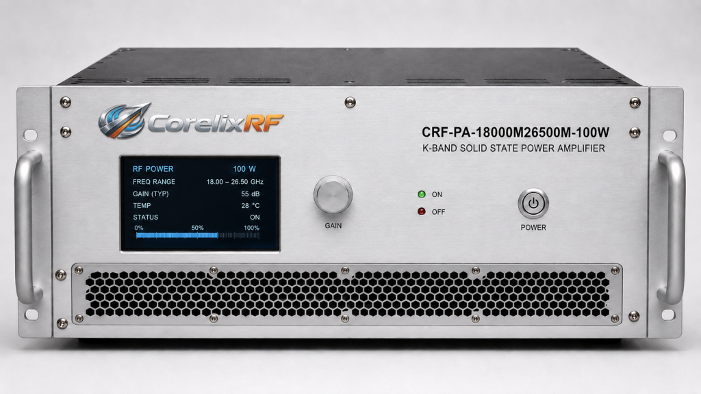
CorelixRF’s CRF-PA-18000M26500M-100W is specified as a GaN solid-state RF power amplifier covering 18 GHz to 26.5 GHz with 100 W rated output power. The source specification lists 50 dB minimum small-signal gain, -6 to +6 dB gain flatness, 15 dB gain control range, 2.92 mm-F input, WR42 output, RS485/LAN control, air cooling, and a 19-inch 4U rack-mount form factor. For teams evaluating a high frequency amplifier , those details are the starting point for a full integration review.
Why the 18-26.5 GHz Band Needs Extra Planning
K-band and adjacent microwave test work can expose weaknesses that are less visible at lower frequencies. Cable loss is higher, adapters are more sensitive, connector repeatability affects measurement confidence, and output interface choices matter. The WR42 output listed in the CorelixRF specification is appropriate for this frequency class, but it also means the mechanical path from the amplifier to the test article must be planned with waveguide routing and flange access in mind.
A 18 GHz to 26.5 GHz amplifier may support communication system validation, microwave component testing, RF interference or EW evaluation, and aerospace control projects. The same amplifier may be used with different loads or fixtures, so a procurement team should confirm the operating frequency points, expected output level, and allowable mismatch cases before ordering.
Core Electrical Parameters
The source data lists 100 W output power, 50 dB minimum gain, -6 to +6 dB small-signal gain flatness, up to 15 dB gain control, 0 dBm maximum input power, -20 dBc typical harmonics, and -60 dBc spurious performance. These figures should be checked against the full RF path. At 18-26.5 GHz, attenuation between the amplifier and the device under test can be substantial, especially if the setup includes couplers, switches, waveguide transitions, or chamber feedthroughs.
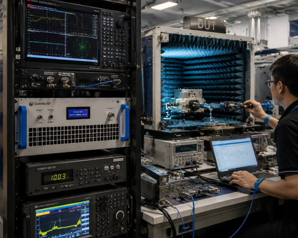
Gain control is useful for leveling, but it should not replace a calibrated power monitoring plan. A good system uses a coupler or measurement path that can verify delivered power at defined points. If forward and reverse power monitoring is needed for the program, request that option during the project review rather than adding an external monitoring chain later.
Rack and Cooling Considerations
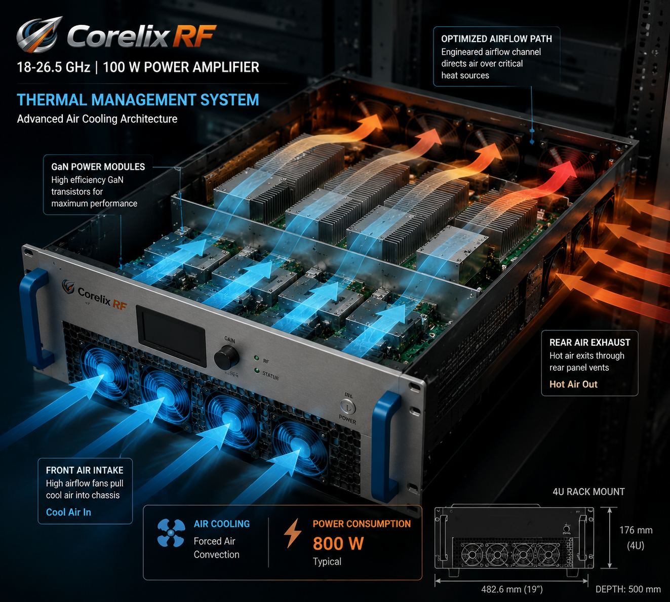
The CRF-PA-18000M26500M-100W is listed as a 19-inch 4U rack-mount amplifier with 29 kg typical weight, AC 220 V input, 800 W typical power consumption, and air cooling. That makes it easier to integrate into a lab rack than a custom chassis, but airflow still requires attention. Leave room for intake and exhaust paths, avoid heat recirculation, and confirm whether the rack will operate in a laboratory, vehicle, shelter, or chamber control room.
Air-cooled microwave amplifiers also benefit from clear service access. Filters, fans, waveguide connections, and front-panel interfaces should remain reachable after installation. If the amplifier will be controlled remotely, physical access is still needed for inspection, waveguide maintenance, and troubleshooting.
Protection and Monitoring Logic
The source specification lists real-time temperature monitoring, real-time current monitoring, optional forward/reverse power monitoring, optional LAN remote monitoring, optional input power detection, and protection for over-temperature, over-current, over-voltage, and VSWR conditions. These are valuable only when integrated into the system control sequence.
For automated test racks, define the alarm state machine. The controller should know what to do if the GaN SSPA reports high temperature, reverse power, or abnormal current. The RF source should be muted before the amplifier is disabled in some systems, while other systems may need an immediate hard inhibit. The exact sequence should be agreed during the control protocol review.
Practical Acceptance Checks
A practical acceptance plan includes output power at multiple frequency points, gain flatness, input drive sensitivity, harmonic and spurious checks, remote command verification, alarm reporting, cooling behavior, and output interface inspection. Because the output is WR42, include the waveguide adapters and loads planned for real operation in the test setup whenever possible.
Also confirm the maximum input drive rule. The specification lists 0 dBm maximum input power. A microwave source or upconverter with a high output setting can overdrive the amplifier if software limits are not enforced. Build input attenuation and source interlocks into the system design if multiple operators will use the rack.
Procurement Questions to Ask
Before ordering, ask whether the final mechanical drawing, test data, and control protocol are available for the project review. Confirm the expected operating duration, frequency step plan, output monitoring method, acceptable load VSWR, remote control requirements, and required documentation. If the amplifier will be part of a larger custom RF amplifier system, provide the switch matrix, coupler, load, and waveguide layout so interface conflicts can be caught early.
FAQ
What output connector is listed for the 18-26.5 GHz 100 W amplifier?
The source specification lists a WR42 output and 2.92 mm-F input.
Is this amplifier rack mountable?
Yes. The referenced configuration is a 19-inch 4U rack-mount unit.
What cooling method is specified?
The source data lists air cooling.
What control interfaces are available?
The referenced configuration lists RS485 / LAN control, with optional LAN remote monitoring and project-specific control support.