
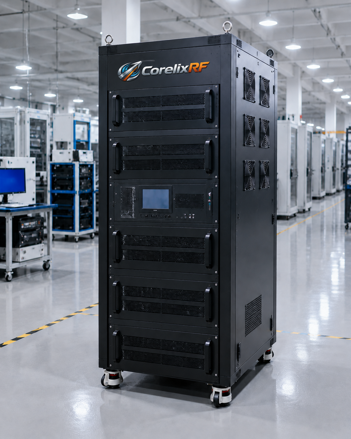
A 2.9-3.5 GHz 25 kW pulsed RF amplifier is a system-level component, not a simple rack accessory. At this peak power level, the amplifier, pulse source, timing logic, cooling plant, waveguide output, load, interlocks, and operator procedure all have to be designed together. CorelixRF’s CRF-PA-2900M3500M-25000W is specified as a GaN pulsed SSPA platform covering 2,900 to 3,500 MHz with 25 kW rated peak output power, 200 us typical pulse width, 20% duty cycle, 74 dB minimum gain, and water cooling.
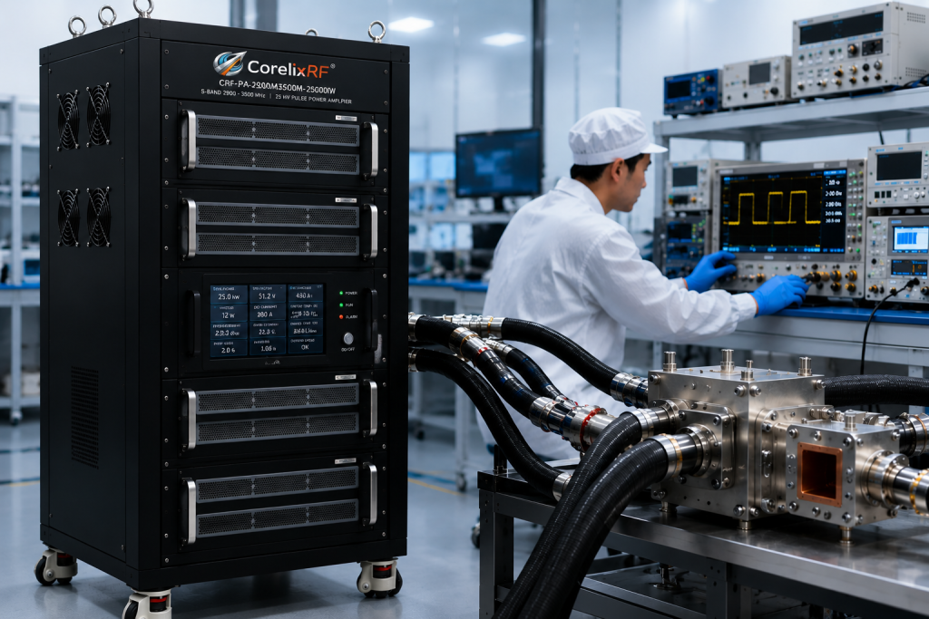
For radar test, aerospace evaluation, RF interference testing, and high-peak-power communication experiments, a pulsed RF power amplifier can provide the burst energy needed for realistic stimulus. The key is to respect the pulse envelope and the thermal design limits from the beginning.
Start With the Pulse Profile
The first integration question is not the connector. It is the pulse profile. The CorelixRF source data lists 200 us typical pulse width and 20% duty cycle. That information should drive the source gating, timing budget, average power calculation, cooling design, and acceptance test method. If the intended waveform uses a different pulse width, duty cycle, repetition interval, or modulation format, the project should be reviewed before hardware is finalized.
A custom RF amplifier review should include the expected pulse train, maximum operating duration, frequency plan, load type, and shutdown behavior. Pulsed amplifiers can be damaged when the timing chain is treated casually. The source, blanking signal, PA enable command, and measurement instruments must agree on when RF is allowed.
RF Interface and Power Path
The specification lists N-Female input and WR284 output. That makes sense for high peak power in this band, but it also requires a mechanical and RF path that can support the planned power. Waveguide bends, adapters, couplers, loads, and test fixtures should be selected for the frequency range and pulse conditions, not only for nominal CW ratings.
The amplifier’s listed electrical values include 25 kW rated peak output power, 74 dB minimum gain, -3 to +3 dB gain flatness, 20 dB gain control range, 5 dBm maximum input power, -10 dBc harmonics, and -60 dBc spurious performance. These values give the test engineer a framework for input drive limits and measurement planning. Input drive must be controlled carefully because 74 dB gain can turn a small source-level error into a large output-level error.
Cooling and Facility Requirements
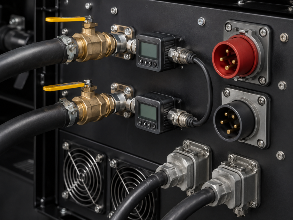
The CRF-PA-2900M3500M-25000W is listed as a water-cooled cabinet platform with AC 380 V three-phase supply, 22,000 W typical power consumption, and 450 kg typical weight subject to final production configuration. These are facility-level requirements. Before issuing a purchase order, confirm available power, cooling water, floor loading, service clearance, emergency shutoff, and the location of the RF load.
Water cooling should be instrumented and interlocked. Flow, inlet temperature, pressure, and leak risk should be reviewed with the same discipline as RF power. If the amplifier is installed in a shielded room, field site, or large test range, cooling hose routing and service access become part of the operational design.
Monitoring, Protection, and Control
The source specification lists real-time temperature monitoring, real-time current monitoring, optional forward/reverse power monitoring, optional LAN remote monitoring, RS485/LAN control, and protection for over-temperature, over-drive, and VSWR alarms. For a high peak power RF amplifier , these features must be connected to actionable system logic.
Define alarm thresholds, operator messages, data logging, and source mute behavior. A reverse power alarm should not simply be recorded after the event. It should drive a known state that protects the amplifier, load, and test article. Similarly, over-drive protection should be paired with source output limits and access control so unauthorized settings cannot exceed the approved input envelope.
Acceptance Testing for Pulsed Operation
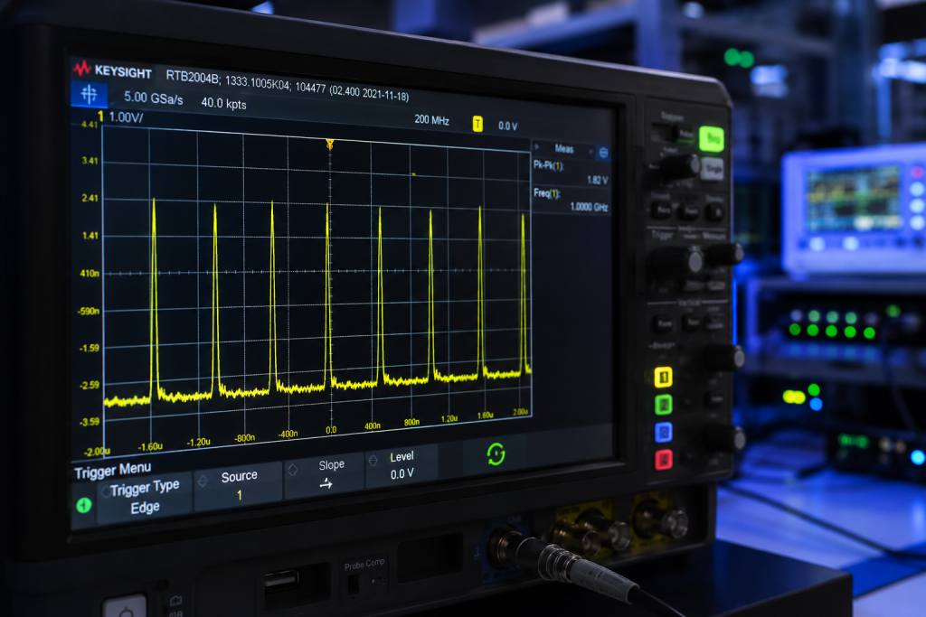
Acceptance testing should verify the amplifier under the pulse conditions that matter to the program. Useful checks include peak output power, pulse flatness, rise/fall behavior where applicable, gain flatness across frequency, harmonic and spurious behavior, cooling response, remote control operation, alarm status reporting, and repeatability over the required test duration.
A pulsed system also needs measurement equipment that can capture peak power accurately. Average power meters alone may not tell the full story. Use sensors, couplers, attenuators, and oscilloscopes or peak power meters rated for the waveform and frequency range.
Procurement Package Recommendations
When requesting a quote, provide the frequency points, pulse width, duty cycle, pulse repetition frequency, modulation type, load VSWR expectation, cooling water conditions, AC power availability, control interface preference, and documentation needs. If the project requires GPIB, input power detection, or forward/reverse monitoring, request those options at the quotation stage.
The goal is to turn the GaN pulsed SSPA into a controlled subsystem with documented limits, not to force a high-power amplifier into an undefined test environment.
FAQ
What peak output power is specified for this pulsed amplifier?
The referenced CRF-PA-2900M3500M-25000W configuration lists 25 kW rated peak output power.
What pulse width and duty cycle are listed?
The source specification lists 200 us typical pulse width and 20% duty cycle.
What output interface is specified?
The amplifier lists WR284 waveguide output and N-Female input.
Is this a water-cooled amplifier?
Yes. The referenced configuration is specified as water cooled.