

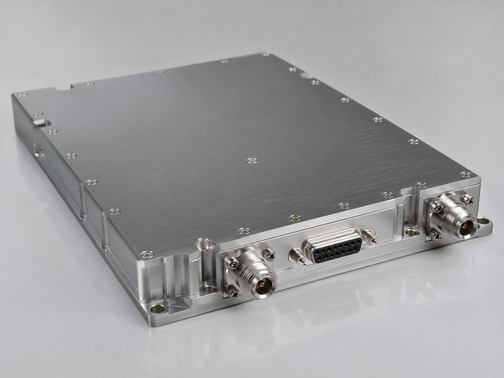
A 400-440 MHz 200 W narrowband UHF RF amplifier is often selected for applications where a compact module must deliver stable power inside a larger RF system. Unlike a full rack-mount broadband amplifier, this class of hardware is usually judged by how cleanly it integrates with a controller, heat sink, power supply, alarm chain, and RF source. CorelixRF’s CRF-PA-400M440M-200W is specified as a GaN solid-state narrowband amplifier covering 400 MHz to 440 MHz with 200 W typical saturated output power, 49 dB minimum gain, gain adjustment, D-Sub control, and optional RS485 monitoring/control.
For teams comparing a narrowband RF amplifier with a broader platform, the advantage is focus. The amplifier is designed around a defined UHF band, so it can be packaged as a compact integration block with specific control and protection behavior.
Core Frequency and Power Requirements
The source specification lists 400-440 MHz frequency coverage, 160 W minimum and 200 W typical output power, 49/51/53 dB min/typ/max gain, 20 dB gain adjustment range with 0.5 dB step, and +24 V to +32 V DC supply with +28 V nominal operation. Operating current is listed as 30 A typical and 36 A maximum, so the DC power path should be sized with margin.
A UHF RF power amplifier in this power class can stress connectors, supply wiring, and thermal hardware even when the RF band seems straightforward. Confirm that the upstream source cannot overdrive the input, and design the supply harness for voltage drop, current handling, and grounding.
M Version, V Version, and Control Options
The specification describes an M version without internal VCO and a V version with an internal VCO source and 10 Hz stepping. It also notes optional RS485 monitoring/control, gain adjustment, forward/reverse power indicators, temperature analog output, alarm reset, and PA enable/disable control. That flexibility is useful, but it means the buyer should define the control model early.
If the amplifier is driven by an external synthesizer, the M version may be appropriate. If a project needs an integrated RF source function within the 400-440 MHz region, the V version may reduce external source complexity. In either case, request the final pinout and control protocol before designing the carrier board or system harness.
Mechanical and Thermal Integration
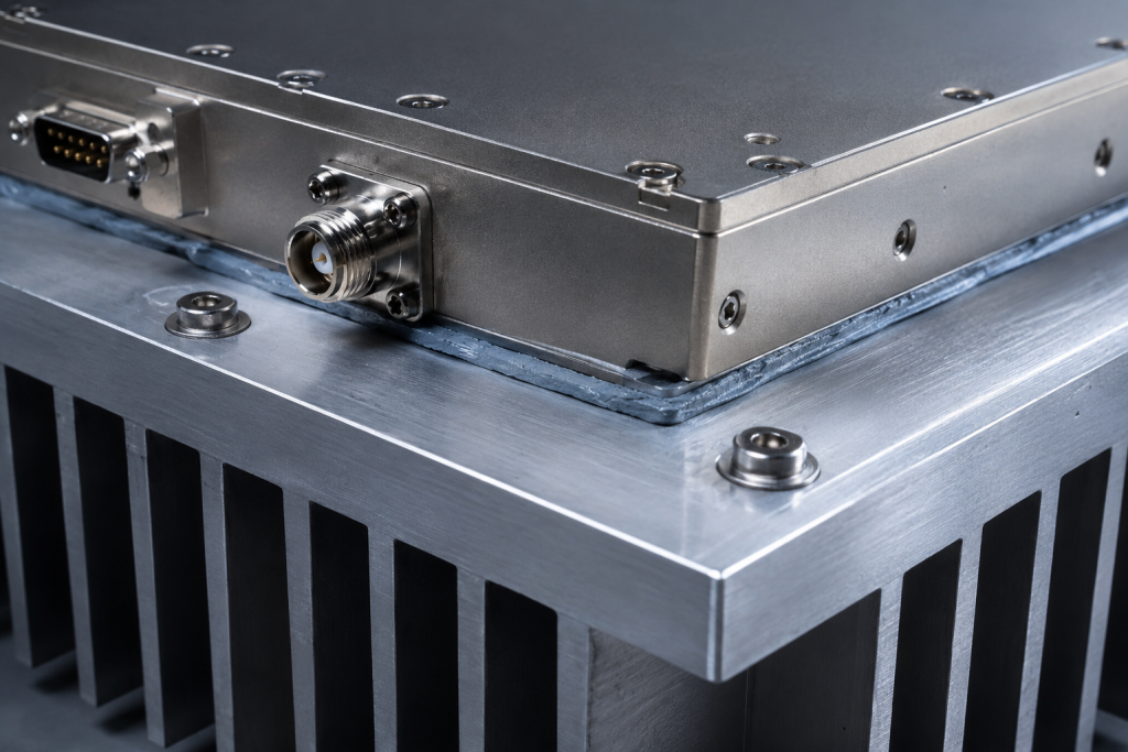
The CRF-PA-400M440M-200W is listed as 200 x 158 x 25 mm with 1.4 kg weight and external heat-sink cooling. This compact form factor is attractive for integrated systems, but it shifts thermal responsibility to the system designer. The module should be mounted to a heat sink that supports the planned duty, ambient temperature, airflow, and mechanical environment.
Do not evaluate this 400 MHz amplifier module only on bench output power. Test it in the mechanical stack-up that resembles the final product. Thermal interface material, screw torque, baseplate flatness, airflow path, and nearby heat sources can all change the operating margin.
Protection Features to Build Around
The source data lists over-temperature shutdown/recovery, over-VSWR locked shutdown, over-voltage lock above 32 V, and over-current lock above 38 A. These features are important, but the host system must expose alarms in a way operators can understand. A locked shutdown should trigger a clear service procedure rather than repeated power cycling.
The D-Sub 15-pin interface supports functions such as PA enable, alarm outputs, alarm reset, optional RS485, gain/power adjustment, and Pf/Pr monitoring where applicable. Use these signals to create a predictable startup sequence: power supply stable, cooling confirmed, RF source muted, PA enabled, source applied, output verified, and alarms monitored.
RF Test and Measurement Planning
Acceptance testing should include output power at representative frequencies, gain response, gain adjustment behavior, harmonic and spurious checks, input VSWR, current draw, temperature output, PA enable timing, and alarm response. The specification lists PA enable/disable time up to 100 us, which may matter for systems with fast RF gating.
If the amplifier will be used in communication systems or RF test sets, also verify modulation behavior under the intended operating condition. The source specification provides amplifier hardware data, but final system performance depends on waveform, drive level, thermal state, and load conditions.
When to Request Custom Review
Request a project review if the amplifier will be placed in a sealed enclosure, operated over a wide temperature range, combined with an internal source, or controlled by custom firmware. Provide the supply design, heat-sink model, duty cycle, RF drive level, alarm handling plan, and connector constraints. A custom RF amplifier discussion can help align the M/M1/V version choice with the final system architecture.
FAQ
What frequency range does the amplifier cover?
The referenced configuration covers 400 MHz to 440 MHz.
What output power is listed?
The source data lists 160 W minimum and 200 W typical saturated output power.
Does it include protection functions?
Yes. The source lists over-temperature, over-VSWR, over-voltage, and over-current protection behavior.
Is external cooling required?
Yes. The module is specified for external heat-sink cooling.