
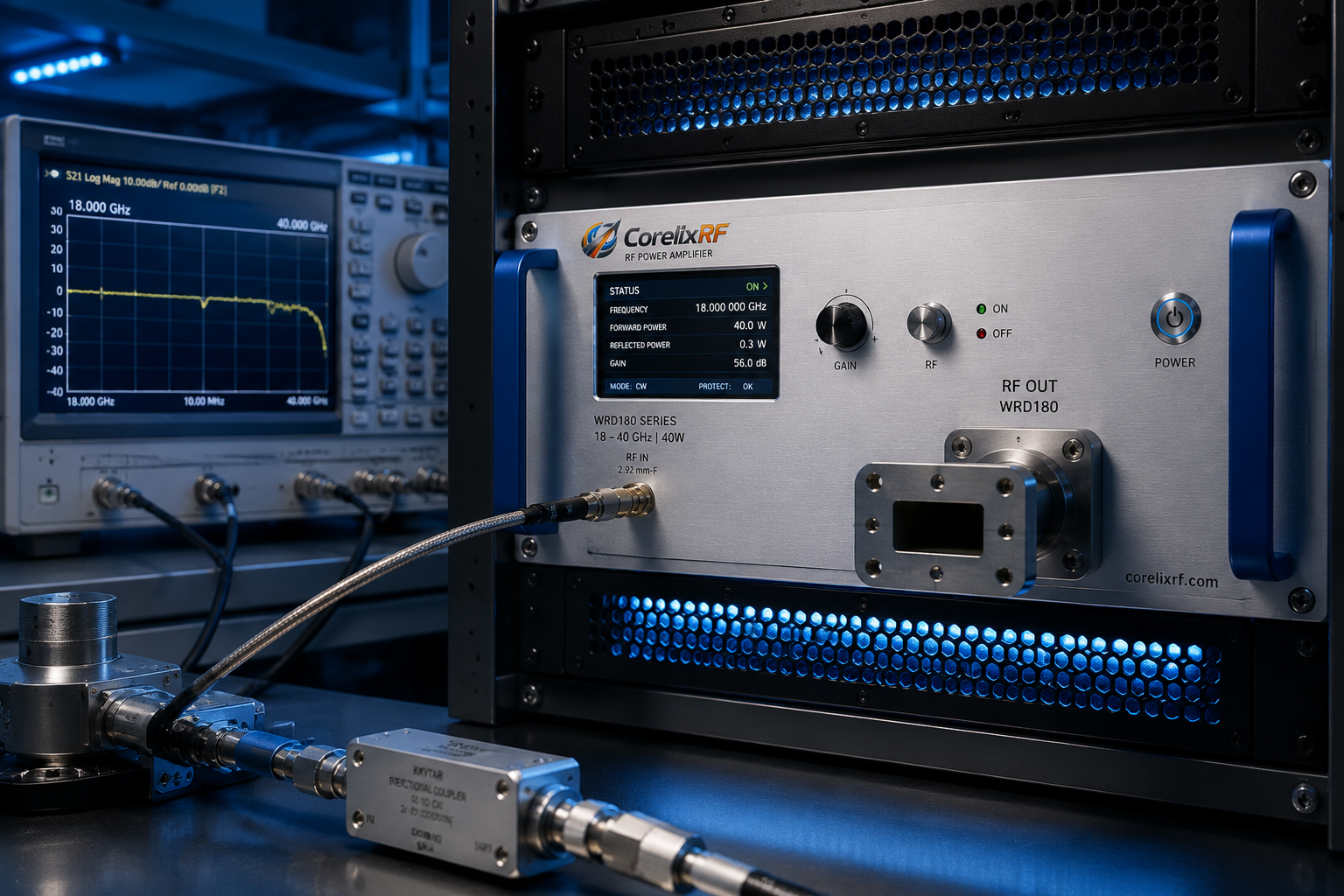
An 18-40 GHz RF power amplifier operates in a frequency range where details that look minor at lower microwave bands can become major integration variables. Connector transitions, waveguide paths, cable loss, rack airflow, control interface, and measurement setup all affect the useful power delivered to the device under test or RF system.
CorelixRF’s 18-40 GHz amplifier platform supports standard 5 W, 20 W, 40 W, and 70 W classes, with project-based review for frequency window, output power, RF connector, waveguide output, control interface, rack structure, and cooling design. The purpose of this article is to help engineering and purchasing teams prepare a stronger review before requesting a quote.
Integration note: start with the actual frequency window
The phrase “18-40 GHz amplifier” can mean a full-band requirement or a focused sub-band inside K, Ka, or adjacent mmWave ranges. The difference matters. A full-band requirement places more pressure on gain flatness, output consistency, and measurement setup. A narrower frequency window may allow a more focused engineering recommendation.
Before selecting a model, define whether the system must cover the complete 18-40 GHz range or only a smaller operating band. Include the required output power at the most important frequencies, not only a single headline number.
Integration note: review connector and waveguide path early
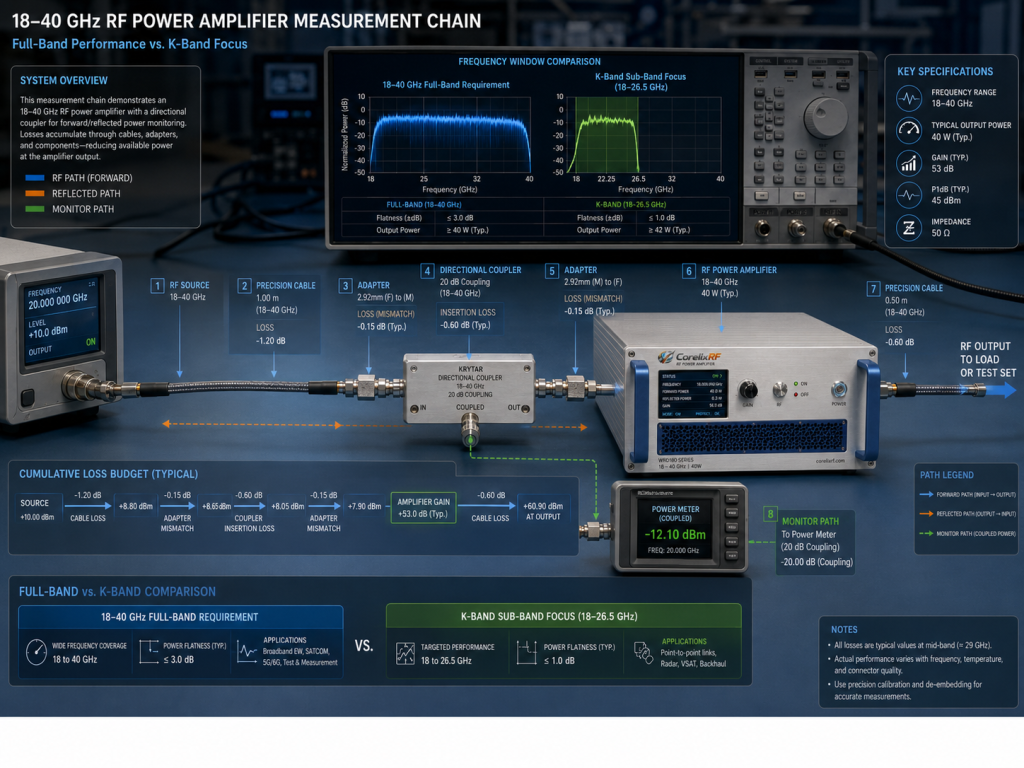
At mmWave frequencies, connector loss and transition quality can shape the delivered RF power. CorelixRF lists 2.92 mm-F input, with 2.92 mm or WRD180 output paths depending on model and project requirements. This means the RF chain should be reviewed as a complete path, including adapters, cables, waveguide transitions, load, couplers, and measurement instruments.
Do not treat connector choice as a small purchasing detail. The connector or waveguide output path can affect cabinet layout, calibration method, and the mechanical design of the test system.
Integration note: account for measurement setup loss
At 18-40 GHz, test setup loss can be substantial. Cable length, adapter count, coupler selection, attenuator rating, and load quality all influence the apparent amplifier performance. When engineers compare datasheet output to measured output at the device under test, setup loss must be included.
For a reliable review, share the intended measurement setup with the amplifier supplier. If the amplifier will be used in a production test system, ask whether model-level curves, gain data, or additional validation information can be provided for the selected configuration.
Integration note: choose power class with thermal reality in mind
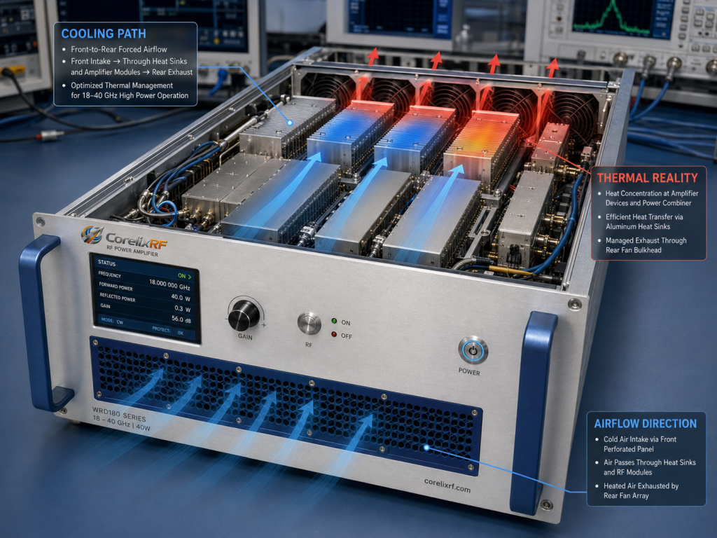
CorelixRF’s standard classes include 5 W, 20 W, 40 W, and 70 W baselines. Higher output is useful only when the rack, cooling, power supply, and operating mode support it. A lower-power mmWave amplifier may be easier to integrate into a compact test environment, while a 40 W or 70 W class may require a more deliberate rack and airflow plan.
Thermal planning should include duty cycle, ambient temperature, installation space, airflow direction, and whether the amplifier will be operated continuously or in controlled test sequences. In mmWave systems, mechanical and thermal planning are not secondary tasks; they are part of the RF design.
Integration note: confirm rack format and control interface
The CorelixRF 18-40 GHz platform references 19-inch rack formats such as 3U, 4U, and 8U depending on model and configuration. Before quotation, confirm rack height, depth constraints, front or rear connector access, cooling path, and service access.
Control interface requirements should also be defined early. RS485, LAN, or GPIB options may be relevant depending on the test environment. Automated stations, remote operation, and system-level integration often require a clearer control plan than a simple front-panel setup.
Where 18-40 GHz amplifiers are commonly reviewed
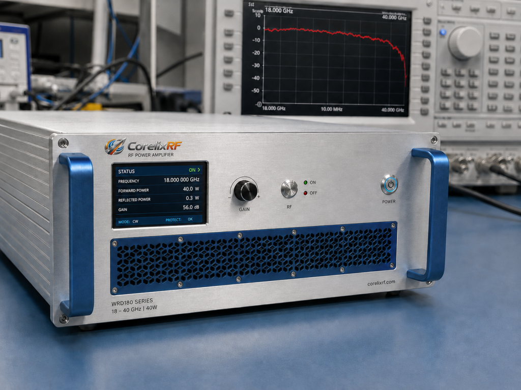
This amplifier class fits mmWave test benches, high-frequency RF validation, radar-related subsystem development, communication hardware evaluation, and custom RF systems where high-frequency power is needed in a controlled format. It can also support engineering programs that need a custom frequency window or a modified mechanical package.
The important point is to avoid treating mmWave amplifier selection like a low-frequency commodity purchase. The best result comes from sharing application context, not only a requested wattage.
Red flags to resolve before purchase
- The requested output power is listed only once, with no band-edge requirement.
- The RF output transition is not defined.
- The rack height is acceptable, but airflow path has not been reviewed.
- The test setup has multiple adapters, but no loss budget.
- Remote control is required, but the command interface is unspecified.
RFQ checklist for mmWave amplifier projects
Include frequency range, required output power by band, input drive level, gain expectations, connector or waveguide preference, rack format, cooling limits, control interface, operating mode, duty cycle, measurement setup, quantity, and documentation needs.
If the system has strict calibration or traceability requirements, state that before quotation. If the amplifier will connect to a specific antenna, chamber, load, or device under test, include that path as well.
FAQ
Is an 18-40 GHz RF power amplifier the same as a Ka-band amplifier?
It may cover Ka-band frequencies, but the exact application depends on the required operating window and output power. A focused Ka-band requirement should be stated clearly.
Why do connector transitions matter so much at mmWave?
Loss and mismatch increase as frequency rises. Connector and waveguide choices can affect delivered power, measurement accuracy, and integration layout.
Should I choose 2.92 mm or waveguide output?
The right output path depends on power class, frequency range, system layout, and downstream hardware. It should be reviewed at the project level.
What documents should I request?
Ask for the datasheet, mechanical outline, connector information, control interface details, and available model-level performance data.