
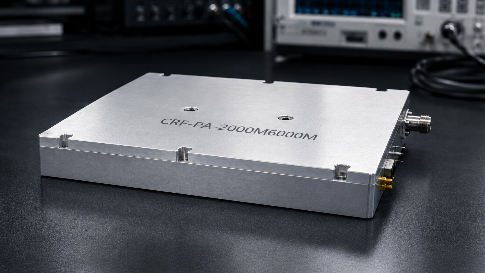
A 2-6 GHz RF power amplifier is a practical building block for broadband RF testing, communication system evaluation, and integrated RF platforms that need defined power across S-band and adjacent frequency ranges. The challenge is not simply finding an amplifier that covers 2,000 to 6,000 MHz. The better question is which power class, gain range, mechanical format, and interface set will reduce risk in the actual test or integration environment.
CorelixRF’s 2-6 GHz amplifier series includes standard 30 W, 50 W, 100 W, 150 W, and 200 W models, with documented electrical and mechanical references for engineering review. That model spread gives buyers a useful starting point: choose enough power for the job without forcing a larger chassis or higher supply requirement than the platform needs.
The short version for buyers
For most 2-6 GHz RF test platforms, the first decision is not brand or price. It is the power class that gives the test team enough margin without oversizing the chassis, supply, and cooling system. CorelixRF’s 30 W, 50 W, 100 W, 150 W, and 200 W options make this a practical comparison rather than a one-size-fits-all purchase.
Why 2-6 GHz coverage is useful
Many RF projects need a broadband amplifier that can support more than one test condition. A 2-6 GHz broadband amplifier can be used for swept validation, subsystem development, lab signal-chain evaluation, and communication-related test setups where the operating point may shift during development.
Compared with a narrowband amplifier, a 2-6 GHz unit gives engineering teams more flexibility during early validation. The tradeoff is that full-band gain behavior, output power consistency, and thermal behavior must be checked carefully. A test platform is only useful if its RF behavior is repeatable enough to support decisions.
Power class comparison
| Power class | Best-fit situation | Main review point |
|---|---|---|
| 30 W | Compact bench or subsystem validation | Input drive and test margin |
| 50 W | General RF lab work | Gain flatness and connector path |
| 100 W | Balanced integration projects | Cooling, supply, and repeatability |
| 150 W | Higher-power test platforms | Airflow and fixture loss |
| 200 W | Maximum-margin broadband setups | Thermal plan and load condition |
Choose the output power class by use case
The CorelixRF 2-6 GHz series spans 30 W to 200 W. A compact 30 W unit may be appropriate for bench evaluation, subsystem development, or space-constrained integration. A 100 W model is often a balanced starting point where output margin and physical size both matter. The 150 W and 200 W classes are better suited for higher-power test environments or integration projects where the RF path needs more headroom.
Power selection should consider required delivered power, cable and fixture losses, duty cycle, load condition, and whether the amplifier will operate continuously or in controlled test intervals. A 200 W unit is not automatically the best choice if the system only needs moderate output and has tight mechanical constraints.
Confirm gain and gain flatness
Gain determines how much input drive is required from the signal source. Gain flatness determines how stable the system response will be across the band. CorelixRF lists typical gain ranges by model, with gain flatness specified for the 2-6 GHz family. For a production test fixture or calibrated bench, this information should be reviewed before final selection.
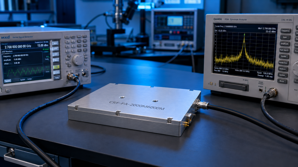
If a signal generator or SDR source drives the amplifier, the input level range should be matched to the selected model. Too little drive may fail to reach the target output. Too much drive may create compression or measurement confusion. A clean RFQ should state the available input drive level and the desired output power range.
Check RF connectors and mechanical fit
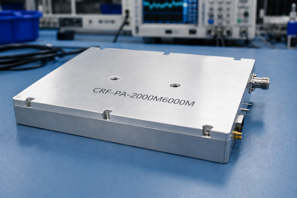
Mechanical details are often discovered too late. For 2-6 GHz modules, confirm RF input connector, RF output connector, control connector, supply voltage, dimensions, weight, and mounting requirements. The CorelixRF 2-6 GHz platform uses compact and higher-power mechanical formats depending on model class, so the chosen unit should be checked against the available enclosure or bench layout.
For system integrators, the connector path matters as much as the amplifier itself. Cable loss, adapter ratings, load condition, and access to connectors after installation should be included in the review.
Treat cooling as a selection parameter
Air cooling may sound simple, but airflow still has to be planned. A 2-6 GHz RF power amplifier installed in a rack, enclosure, or dense test fixture may face different thermal conditions than a module operating on an open bench.
Before ordering, define ambient temperature, operating duration, duty cycle, airflow limitations, and whether the amplifier will sit near other heat-generating hardware. Thermal planning protects performance and helps avoid redesign after the amplifier arrives.
Where this amplifier class fits
A 2-6 GHz RF power amplifier can support RF testing and validation, communication system development, signal-chain characterization, antenna-path evaluation, and broadband hardware integration. It can also serve as a starting point for a custom RF amplifier review if the project needs a specific sub-band, connector change, interface adjustment, or mechanical package.
The best selection process starts with the application. A lab validation team may prioritize documented curves and repeatability. A system integrator may prioritize mechanical drawings and connector placement. A procurement team may need datasheets, test data, and a clear sample-to-production path.
Buyer checklist before quotation
- Required frequency span inside 2-6 GHz
- Target output power at the device, not only at the amplifier output
- Signal source and available input drive
- Duty cycle and expected operating time
- Connector and cable path
- Cooling and enclosure limits
- Quantity, project stage, and requested documentation
What to send for engineering review
Include target frequency range, required output power, operating mode, duty cycle, input drive level, supply voltage preference, RF connector preference, cooling condition, dimensions, quantity, and project stage. If the amplifier will be part of a larger RF system, include the upstream signal source and downstream load or antenna condition.
The more specific the request, the easier it is to recommend a standard model or identify a customization path.
FAQ
What is the best 2-6 GHz RF power amplifier for a test bench?
It depends on required output power, input drive, duty cycle, and mechanical limits. The 30 W and 100 W classes are common starting points, while higher power classes should be reviewed for thermal and supply requirements.
Can 2-6 GHz amplifiers be customized?
Project-based customization may be reviewed for frequency window, connector, control interface, or mechanical constraints.
Why does gain flatness matter?
Gain flatness affects calibration and repeatability across the full frequency range, especially in swept or multi-frequency testing.
What should procurement request before ordering?
Procurement should request the datasheet, mechanical outline, available performance curves, lead time, and any model-specific validation documentation.