
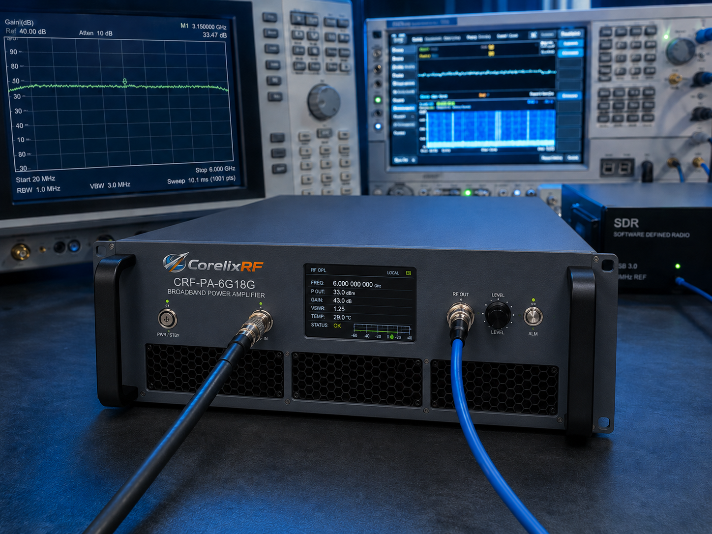
A 6-18 GHz broadband RF power amplifier is rarely selected by output power alone. For a bench test system, an SDR-driven RF chain, a microwave front end, or a rack-level integration project, the real question is whether the amplifier can deliver usable power across the required band while fitting the available connector path, cooling method, control interface, and validation workflow.
CorelixRF’s 6-18 GHz amplifier platform is positioned for engineers who need datasheet-supported power classes across the full 6-18 GHz range, with GaN solid-state design, RS485 or LAN control options, and compact-to-rack mechanical formats. The selection process should be treated as an engineering review, not only a catalog lookup.
Selection Checkpoint 1: Full-band output behavior
The first check is whether the required output power applies across the full band or only around a narrower operating window. A system that needs 100 W near 8 GHz may not have the same margin at 17.5 GHz. For broadband test environments, ask for curves or measured data that show output power and gain behavior across the operating span.
This is especially important for EMC-related test setups, microwave subsystem evaluation, and multi-band RF front ends. When a project requires a guaranteed minimum at band edges, the RFQ should state that requirement directly instead of assuming a headline power number covers every frequency.
Selection Checkpoint 2: Gain flatness before calibration
Gain flatness affects calibration, link budget, repeatability, and how much correction is required in the upstream signal source. A broadband microwave amplifier with 12 GHz instantaneous coverage can introduce gain variation that matters in swept testing or waveform playback.
For the CorelixRF 6-18 GHz series, gain flatness depends on the power class. The practical step is to request the model-level gain curve before finalizing the amplifier. If the system includes an SDR source, signal generator, attenuator chain, or automated test software, gain flatness should be reviewed together with the rest of the RF chain.
Selection Checkpoint 3: RF interface and hardware path
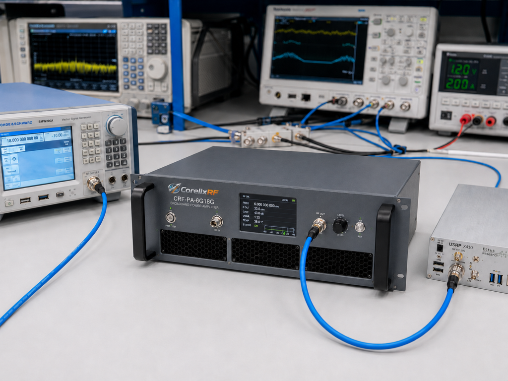
Connector selection can decide whether an amplifier is easy to integrate or becomes a source of avoidable loss and rework. Across 6-18 GHz projects, common review points include SMA input, N-type output, waveguide transitions for higher power classes, cable loss, adapter ratings, load condition, and rack layout.
For a 6-18 GHz RF power amplifier, the RF output connector should be confirmed by model and power class. Do not leave this until purchase order stage. Connector transitions, cable routing, and load protection can affect delivered power and measurement confidence.
Selection Checkpoint 4: Cooling and chassis constraints
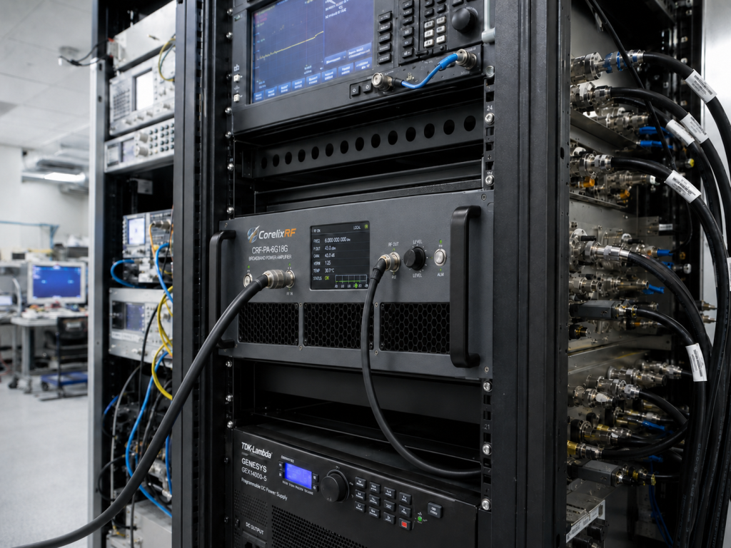
High-power microwave amplifiers convert thermal planning into a project risk item. A compact lab setup may be comfortable with a lower-power module, while a rack-level system may require defined airflow, front-to-back cooling, cabinet spacing, and duty-cycle review.
CorelixRF offers 6-18 GHz configurations from compact lower-power units to rack formats. Before selecting the final unit, define ambient temperature, duty cycle, expected operating time, rack space, and airflow direction. If the amplifier will run in an enclosure, vehicle platform, shielded room, or automated station, mechanical drawings should be reviewed early.
Selection Checkpoint 5: Control and monitoring
Manual operation may be enough for simple bench validation, but many engineering teams need remote control and monitoring. RS485 and LAN options are relevant when the amplifier must be integrated into automated test software, a remote RF system, or a larger front-end platform.
The control discussion should include enable/disable logic, gain control if required, monitoring needs, alarms, interlock behavior, and the user’s preferred command path. This is where direct engineering communication matters: the right answer depends on how the amplifier will be operated after installation.
Selection Checkpoint 6: Application context
A 6-18 GHz GaN amplifier may be used for RF testing, communication system evaluation, microwave signal transmission, or SDR-based waveform amplification. Each use case changes the selection logic.
For RF testing and validation, repeatability and measured curves may matter more than maximum output. For SDR integration, input drive level, linearity expectation, and control interface become important. For a high-power RF front end, thermal behavior, load protection, and mechanical packaging may dominate the review.
What to include in the RFQ
To get a useful recommendation, provide frequency range, target output power, operating mode, duty cycle, input drive level, supply preference, RF input and output connector requirements, cooling limits, control interface, rack or module format, and any required test documents.
If the requirement is not a standard full-band case, explain the exact frequency window. A narrower band or custom connector layout may be easier to support than a vague “6-18 GHz amplifier” request.
FAQ
Is a 6-18 GHz amplifier always better than a narrower-band unit?
Not always. A full-band amplifier is useful when the system must cover a wide frequency span. If the application only uses a narrow band, a custom or narrower-band review may improve fit, cost, or performance margin.
What information matters most before quotation?
Frequency range, required output power across the band, duty cycle, input drive, connector path, cooling method, and control interface are the most important starting points.
Can a 6-18 GHz amplifier work with an SDR source?
Yes, but the SDR output level, waveform type, duty cycle, required linearity, and amplifier input drive range should be reviewed together.
Should I request test data before ordering?
For engineering projects, yes. Curves or model-level measured data help confirm gain behavior, output power, and integration risk before purchase.
Next engineering step
If the project is still at architecture stage, send the frequency span, required output level, source drive, duty cycle, connector path, rack limits, and control preference. If the project is already in procurement, attach the existing RF chain diagram or system block diagram so the amplifier recommendation can be checked against the real signal path.