
A high-power pulsed RF amplifier is usually bought after someone says, “We need more peak power.” That sentence is never enough. At 25 kW, the amplifier touches the facility, cooling loop, waveguide layout, timing architecture, safety procedure, and data logging plan. A better procurement conversation begins with questions.
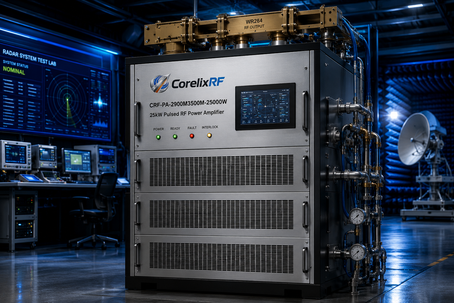
The CorelixRF CRF-PA-2900M3500M-25000W is a 2.9-3.5 GHz GaN pulsed SSPA rated for 25 kW peak output power. The datasheet lists 200 microseconds typical pulse width, 20% duty cycle, 74 dB minimum gain, 20 dB gain control, N-Female RF input, WR284 output, RS485/LAN control, water cooling, AC 380 V +/-10% three-phase input, and 22,000 W typical power consumption. It is a cabinet-level amplifier for serious S-band pulsed test systems.
- What Pulse Are You Actually Trying to Reproduce?
Peak power is only one coordinate. The amplifier must be reviewed against pulse width, duty cycle, pulse repetition interval, waveform type, burst duration, and total test time. The CRF-PA-2900M3500M-25000W is specified around a 200 microsecond typical pulse width and 20% duty cycle. If the required waveform is outside that envelope, the application should be reviewed before quotation.
- Is the Load Path Waveguide-Ready?
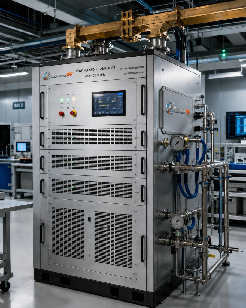
The amplifier uses WR284 output. That means the RF path is not a casual coax run. The system needs waveguide routing, appropriate flanges, directional couplers, high-power loads, antenna transitions if used, and mechanical support. A small mechanical problem can become a high reflected-power problem.
- What Reflected Power Conditions Are Realistic?
Radar and EW test setups often involve changing antennas, fixtures, or environmental conditions. VSWR protection and alarm functions are listed in the datasheet, but the expected mismatch should still be described. If the amplifier will see a dynamic antenna environment, say so early.
- Who Owns Cooling?
The amplifier is water cooled. Cooling is not an accessory; it is part of the RF specification. Flow rate, inlet temperature, coolant quality, heat rejection, leak detection, and service access should be assigned to a responsible team before the amplifier arrives.
- Does the Facility Support the Power Requirement?
The datasheet lists AC 380 V +/-10%, 50/60 Hz, with 22,000 W typical consumption. Verify electrical service, grounding, breaker capacity, cable routing, and emergency-off requirements. A 25 kW pulsed amplifier should not be surprised by its building.
- How Will Operators Control It?
RS485 and LAN control are listed. Decide whether the amplifier will be operated from a local panel, automated test software, or a remote control room. Define command states, fault handling, startup order, shutdown order, and who can reset a trip.
- What Data Must Be Logged?
For high-power pulsed work, data logging can save days of uncertainty. Temperature, current, forward power, reverse power where configured, alarm state, pulse settings, and source drive should be captured with time stamps. Optional forward/reverse power monitoring and LAN remote monitoring should be reviewed if traceability matters.
- What Is the Driver Chain?
With 74 dB minimum gain and maximum input power listed at 5 dBm, the upstream source must be controlled. The system may need a driver, attenuator, limiter, switch, or interlock. Pulse timing should be validated across the full chain rather than assumed from the signal generator screen.
- What Safety Boundaries Are Required?
A 25 kW pulsed S-band system can create hazardous RF fields. The test plan should include access control, interlocks, signage, load verification, personnel procedure, and failure response. Protection inside the amplifier helps the hardware, but it does not replace site safety engineering.
- What Would Make Acceptance Testing Clear?
Before ordering, define the acceptance test. Include frequency points, pulse profile, output measurement method, gain setting, allowed tolerance, cooling condition, and control interface behavior. If the acceptance test uses a different load path than the final installation, document both.
Why This Question-Based Format Works
Engineers do not need another paragraph saying high power is important. They need the hidden questions that prevent late-stage integration problems. The CRF-PA-2900M3500M-25000W gives those questions real numbers: 2.9-3.5 GHz, 25 kW peak, 200 microseconds, 20% duty, WR284, water cooling, RS485/LAN, and AC 380 V power.
Internal Links to Use When Publishing
Link pulsed RF amplifier to the CorelixRF pulsed amplifier category. Link radar RF amplifier to a radar or S-band product page if available. Link high power RF testing to the relevant application page. Link custom RF amplifier to the contact or RFQ page.
FAQ
What is the most important specification besides peak power?
Pulse width and duty cycle are critical because they define the thermal and electrical operating envelope.
Why does WR284 output matter?
It determines the waveguide path, coupler selection, load choice, and mechanical integration approach.
Should LAN control be requested?
LAN control is useful when the amplifier will be part of automated testing or installed away from the operator.
What is the CTA?
Request a Pulsed Amplifier Application Review – https://corelixrf.com/contact/