
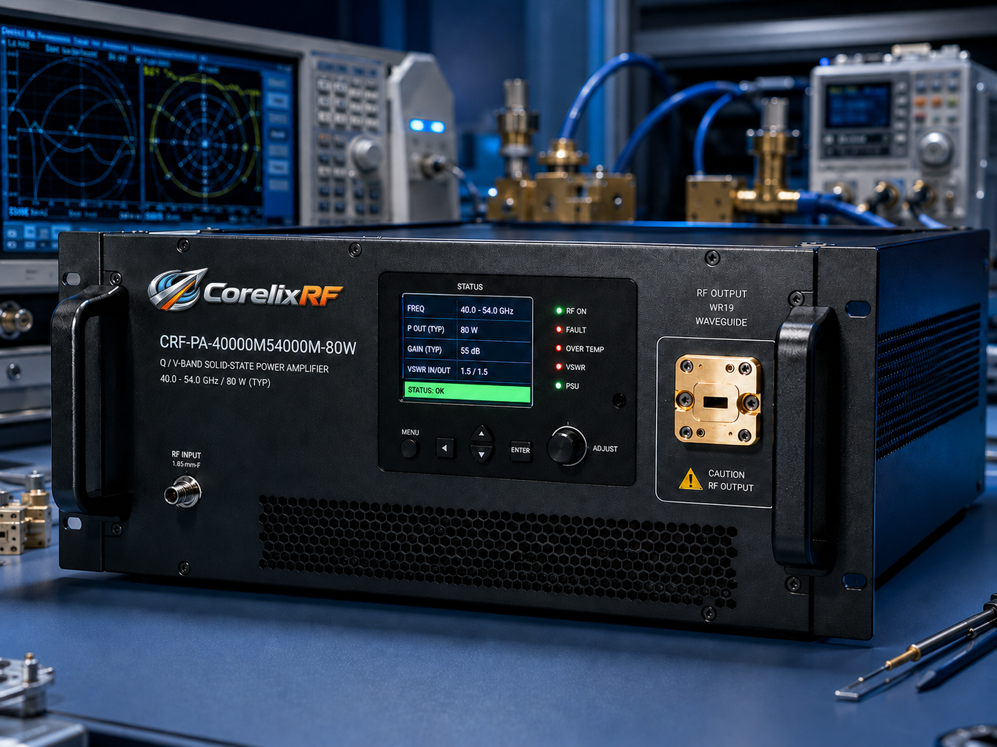
At millimeter-wave frequencies, two engineers can measure the same amplifier and both be honest while getting different answers. One measured at the amplifier flange. The other measured after a waveguide run, adapter, coupler, and antenna feed. Neither number is wrong, but only one may describe the power available to the device under test. This is why a 40-54 GHz amplifier conversation should begin with the reference plane.
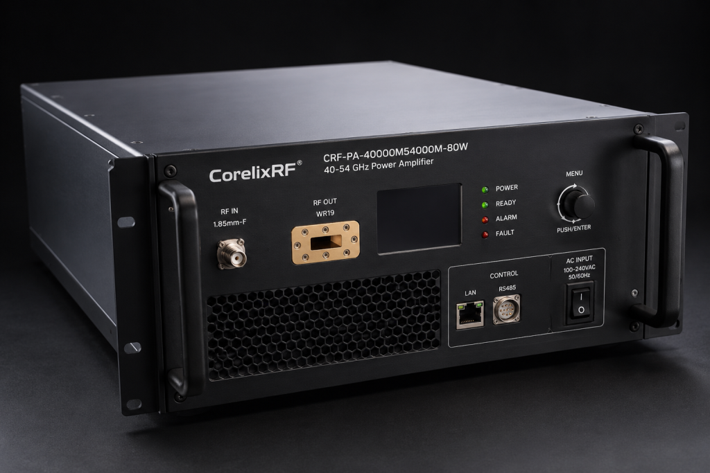
The CorelixRF CRF-PA-40000M54000M-80W is a wideband mmWave GaN SSPA covering 40 GHz to 54 GHz with 80 W rated output power. It provides 50 dB minimum small-signal gain, 15 dB gain control, 1.85 mm-F input, WR19 output, RS485 and LAN control, AC 220 V input, forced-air cooling, and a 19-inch 5U form factor. Those facts are useful, but they become meaningful only when the test system defines where power, flatness, and mismatch are measured.
The Reference Plane Problem
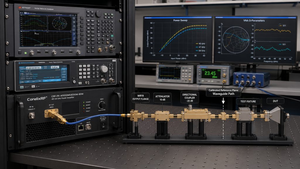
In a low-frequency coaxial bench, engineers sometimes get away with casual assumptions about cable loss. At 40-54 GHz, that habit becomes expensive. Adapter loss, waveguide loss, coupler directivity, flange repeatability, and connector wear can all affect results. If the amplifier is specified as 80 W but the test article receives a lower value after the path, the difference may be normal insertion loss rather than amplifier underperformance.
The solution is simple in principle: define the reference plane before testing. It might be the WR19 output flange, the end of a waveguide run, the antenna input, or the field point inside an OTA setup. Once the reference plane is chosen, every sweep, power reading, and flatness discussion should point back to it.
Where Gain Control Helps
The CRF-PA-40000M54000M-80W includes 15 dB gain control. In a calibrated mmWave bench, gain control can be used to compensate for planned test levels, not to hide uncertainty. For example, the engineer can create a table of frequency, source level, amplifier gain setting, measured output at the reference plane, and temperature state. That table becomes the operating recipe.
Because the datasheet lists 50 dB minimum small-signal gain and wideband gain variation, source leveling and external monitoring remain important. A good test rack does not assume the amplifier alone creates a flat delivered field or load power. It measures the system.
Coax In, Waveguide Out
The 1.85 mm-F input and WR19 output tell a story about the amplifier’s role. Low-level RF can enter through a precision coaxial path, while the high-power output leaves through waveguide. The transition between those worlds requires discipline. The input side needs clean source power and connector care. The output side needs correct waveguide hardware, power-rated components, and controlled flange interfaces.
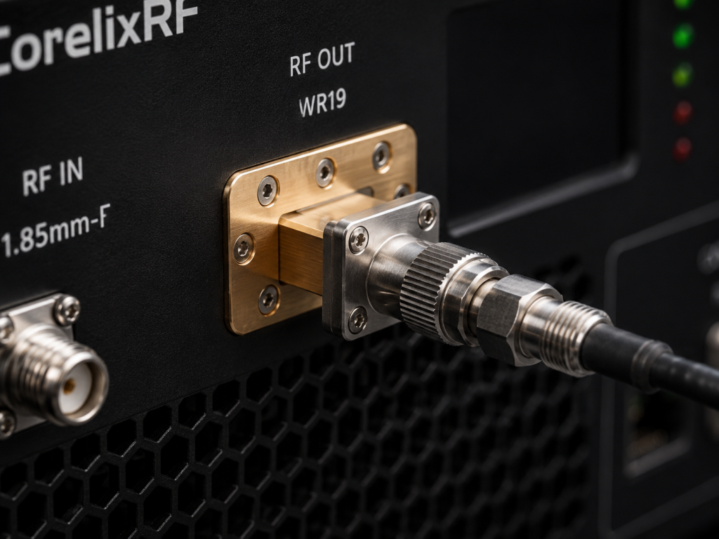
If an engineer changes an adapter or moves a coupler, the calibration may no longer represent the setup. For recurring production or qualification tests, fixture configuration should be controlled with photos, part numbers, and revision notes.
Thermal Stability and Repeatability
The amplifier is packaged as a 19-inch 5U unit with forced-air cooling. In a crowded rack, airflow can vary between the top and bottom of the cabinet. Temperature changes can affect gain, protection behavior, and long-sweep consistency. Real-time temperature and current monitoring should be used as part of the test context, especially when comparing data collected on different days.
The datasheet also lists optional forward/reverse power monitoring and input power detection. Those features are valuable for mmWave work because they help distinguish an amplifier issue from a path issue. If reverse power rises after a fixture change, the problem may be the load path rather than the amplifier.
Best-Fit Applications
This platform fits Q/V-band component testing, mmWave communications development, RF interference testing, aerospace control evaluation, and high-frequency instrumentation. It is especially useful when the lab needs high power across a broad 40-54 GHz span and wants remote control through RS485 or LAN.
To request a useful review, provide the operating frequencies, reference plane, required power at that plane, waveguide path, duty profile, modulation or CW details, control interface, rack airflow plan, and monitoring requirements. If the project includes OTA testing, include antenna gain, distance, field target, and chamber constraints.
Internal Links to Use When Publishing
Link mmWave power amplifier to the CorelixRF millimeter-wave amplifier category. Link 40-54 GHz amplifier to the closest product page. Link microwave amplifier to the microwave category. Link RF testing to the testing application page and Contact CorelixRF to the contact page.
FAQ
Why is the reference plane important at 40-54 GHz?
Because waveguide, adapters, couplers, and fixtures can introduce meaningful loss and uncertainty.
What output interface does the amplifier use?
The amplifier uses WR19 waveguide output.
What control options are listed?
RS485 and LAN control are listed in the datasheet.
What is the CTA?
Discuss a 40-54 GHz Test Setup – https://corelixrf.com/contact/