
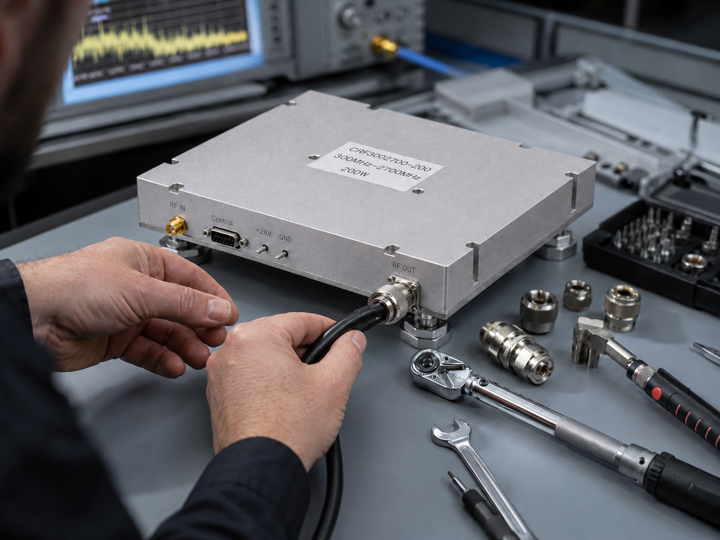
SDR projects are wonderfully flexible until the RF output needs to become real power. Then the flexible waveform meets supply current, heat sinking, gain control, VSWR, switching time, and spectral quality. A broadband amplifier module can make the system compact, but only if the integrator treats it as a controlled RF subsystem rather than a black box bolted to the chassis.
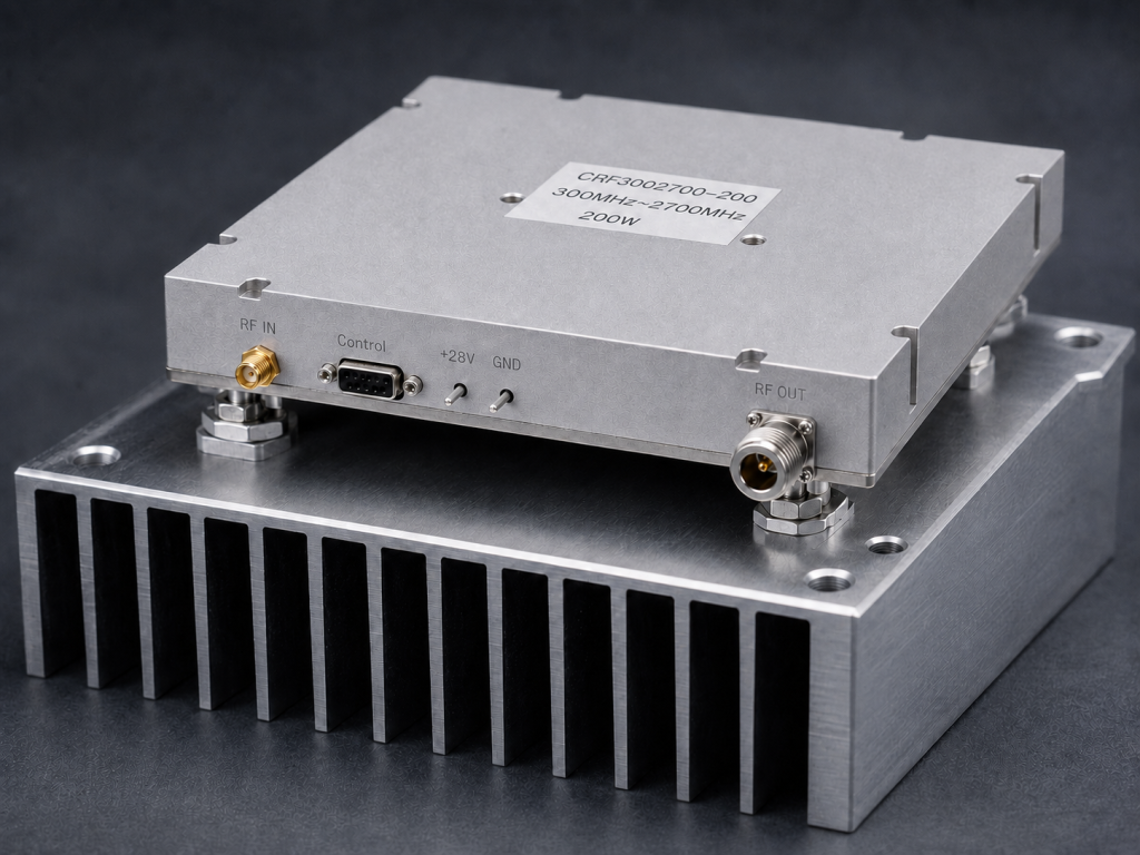
The CorelixRF CRF-PA-300M2700M-200W covers 300 MHz to 2700 MHz and delivers 200 W rated CW output power. It is a GaN SSPA module with up to 200 MHz instantaneous bandwidth, 44-54 dB small-signal gain, +/-4 dB gain flatness, 20 dB gain adjustment in 0.5 dB steps, 10 microseconds PA enable/disable time, SMA-F input, N-F output, +28 V nominal supply, and a compact 200 x 158 x 25 mm mechanical size. The datasheet lists 1.4 kg weight and external heat-sink cooling.
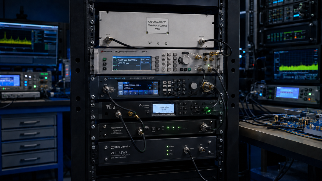
Checklist Item 1: Define the Waveform Before the Power Target
A 200 W CW rating does not automatically mean a complex OFDM waveform can be transmitted at 200 W average power while meeting every spectral objective. Define modulation, occupied bandwidth, crest factor, EVM target, adjacent-channel requirement, and test duration. If the waveform is only for receiver stress, the acceptance criteria may be different from a communications link with spectral mask requirements.
Checklist Item 2: Reserve Thermal Space Early
The module is compact, but compact does not mean thermally optional. It requires an external heat sink. Mechanical engineers should receive the power dissipation assumption, mounting surface requirements, airflow concept, ambient temperature range, and service conditions before the enclosure is frozen. Heat sink mass, fin orientation, fan selection, and thermal interface material can determine whether the amplifier works reliably.
Checklist Item 3: Protect the Source From Its Own Software
Many SDRs and signal generators can output unexpected transients during initialization, waveform loading, frequency switching, or script errors. With 44-54 dB gain, an apparently small source event can become a large RF event. The 10 microseconds PA enable/disable feature should be used intentionally. Coordinate the PA enable line with waveform readiness and source mute behavior.
Checklist Item 4: Use Gain Control as a Calibration Tool
The amplifier provides 20 dB gain adjustment with 0.5 dB step. In a test rack, that can become part of a calibration table. Record frequency, source level, amplifier gain setting, measured output power, temperature state, and load condition. This is more repeatable than asking the operator to remember where the signal generator happened to be set last time.
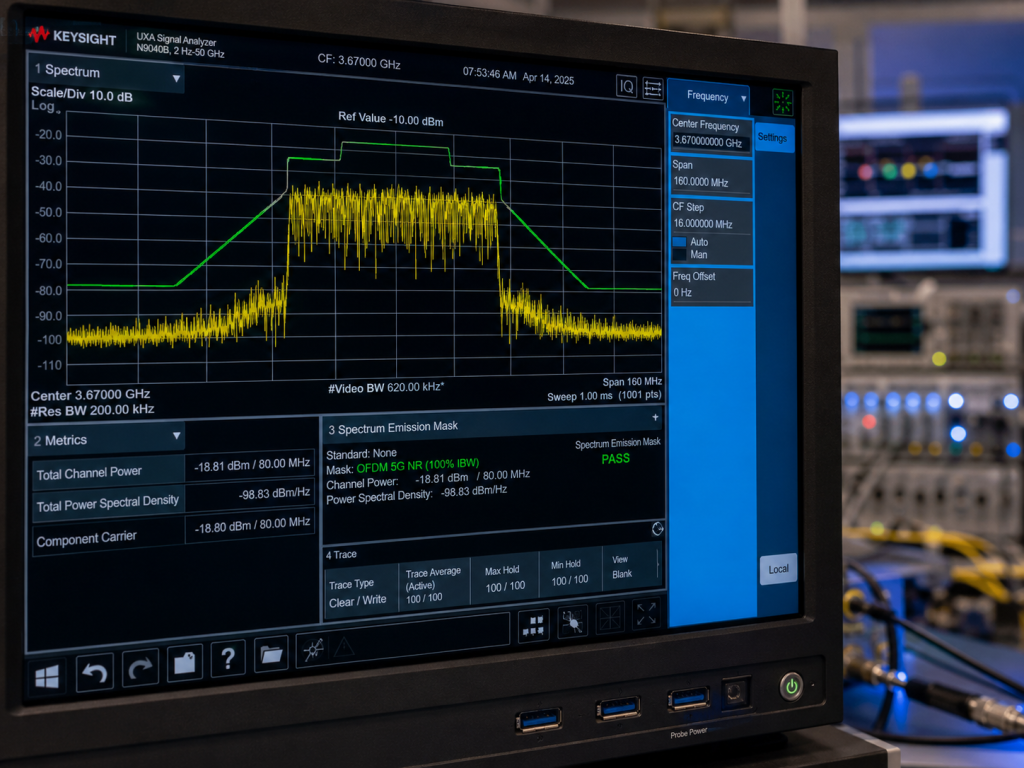
Checklist Item 5: Decide How Much Monitoring Is Needed
The datasheet describes optional RS485 monitoring/control, forward/reverse power monitoring, alarm output, hardware reset support, and analog temperature reporting. A quick prototype may not use all of that. A fielded system or automated rack usually should. Monitoring turns mysterious failures into diagnosable events.
Checklist Item 6: Plan for Bad Loads
The protection list includes over-temperature shutdown/recovery, over-VSWR locked shutdown, over-voltage lock above 32 V, and over-current lock above 38 A. These details matter because SDR systems often change antennas, filters, cables, and fixtures. The system software should know what to do after a fault. A locked shutdown is useful only if the recovery procedure is clear.
Checklist Item 7: Match Connectors to the Whole Chain
The module uses SMA-F input and N-F output. That is convenient for many integration paths, but the final system must still verify cable power ratings, adapter count, connector torque practice, filtering, coupler placement, and output load rating. Connector convenience should not hide RF power discipline.
Checklist Item 8: Ask for the Right Customization
CorelixRF can review interface options such as PA_EN, alarm output, hardware reset, optional RS485, gain/power adjustment, analog temperature reporting, and forward/reverse power monitoring. The most useful request is not “send a quote.” It is a compact system description with frequency range, output power, waveform, instantaneous bandwidth, supply, heat sink concept, control method, and environmental limits.
Internal Links to Use When Publishing
Link SDR RF amplifier to the most relevant SDR or broadband amplifier page. Link broadband RF amplifier to the 300-2700 MHz product/category page. Link custom RF amplifier to the RFQ or contact page. Link GaN SSPA to the GaN amplifier category if available.
FAQ
Why is instantaneous bandwidth important for SDR?
It helps determine whether the amplifier can support the occupied bandwidth of broadband or OFDM-type signals.
Why does PA enable timing matter?
It lets the system coordinate RF output with waveform readiness and source mute behavior.
What cooling does this module require?
The datasheet specifies an external heat sink.
What is the CTA?
Get an SDR Amplifier Integration Review.