
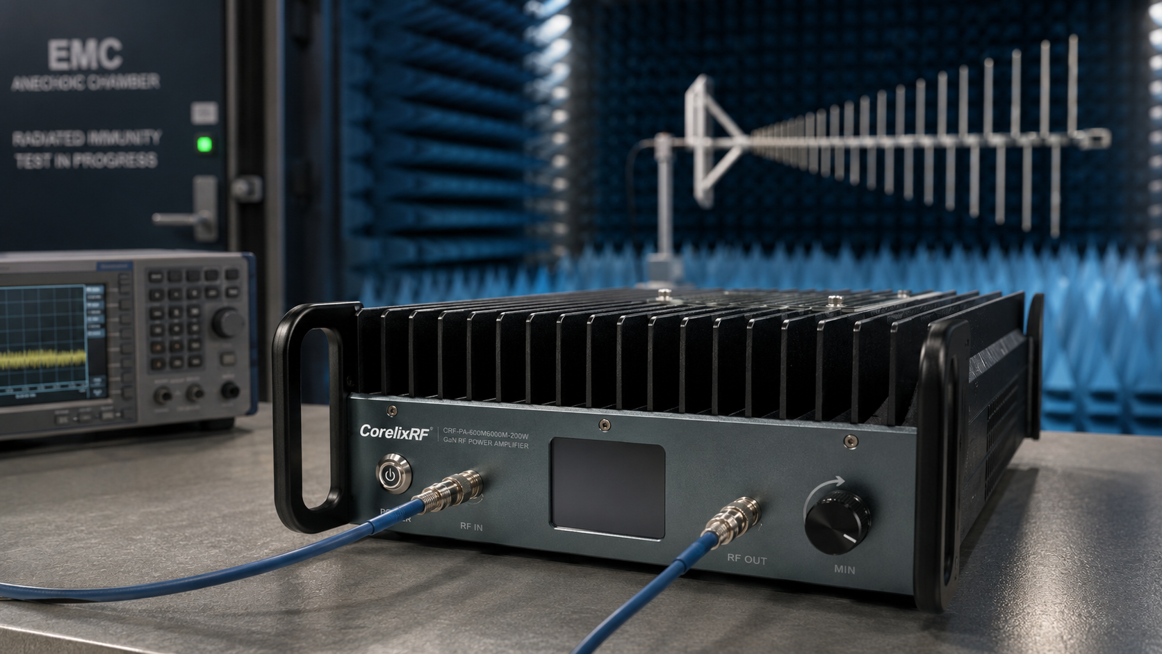
A radiated immunity bench is not a pile of instruments. It is a repeatable method for turning a signal source into a controlled RF environment. The amplifier matters, but so do the antenna, coupler, field probe, chamber layout, cable loss, mismatch behavior, and the way the operator steps through a frequency sweep. If the setup changes every time a new band is tested, the lab spends more time debugging the bench than testing the device.
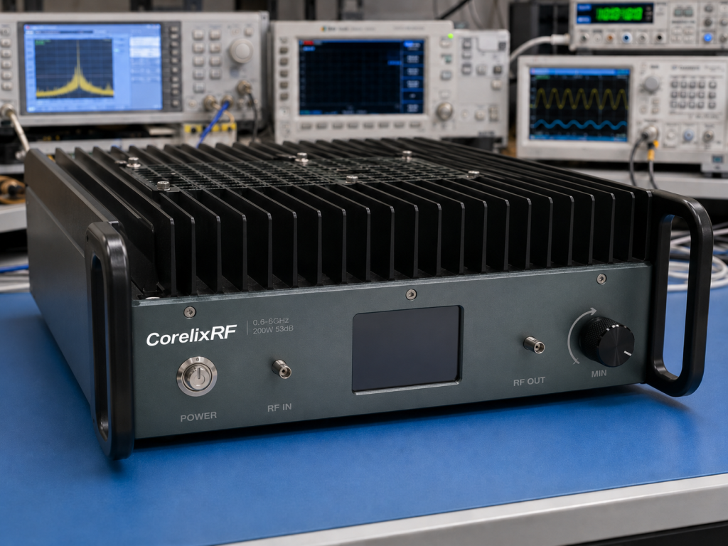
This article uses the CorelixRF CRF-PA-600M6000M-200W as the anchor for a practical 0.6-6 GHz immunity and RF stress setup. The amplifier covers 0.6 GHz to 6 GHz, delivers 200 W rated output power, and uses a GaN SSPA architecture. The datasheet lists 53 dB minimum gain, +/-4 dB gain flatness, 20 dB gain control, SMA-F input, N-F output, RS485 control, +28 V DC supply, and a 440 x 470 x 180 mm form factor requiring system-level forced-air cooling.
Start With the Test Objective, Not the Amplifier
The first decision is the exposure objective. Are you trying to reproduce a radiated immunity condition, drive a broadband antenna, stress a communications receiver, or evaluate a system-level RF interference scenario? The same 0.6-6 GHz amplifier can support all of those workflows, but the surrounding hardware changes.
For a radiated setup, the amplifier output may feed a directional coupler and antenna. The system then needs field probes, antenna factors, chamber loss data, and a leveling method. For a conducted setup, the amplifier may feed injection hardware, attenuators, limiters, or couplers. In both cases, the amplifier should be selected with enough gain control to tune power without constantly changing source settings.
The CRF-PA-600M6000M-200W gives the integrator 20 dB of gain control. That is useful during calibration because the engineer can hold the signal generator in a clean operating region while using amplifier gain to trim delivered power. It also helps when switching between antennas with different gain or fixtures with different losses.
A Practical Sweep Workflow
A disciplined sweep usually has five stages. First, verify the unloaded RF path at low drive. Second, add the coupler or monitoring path and confirm forward power reading. Third, connect the antenna or conducted fixture and check reflected power behavior. Fourth, run a low-level frequency sweep to find unexpected resonances or loss peaks. Fifth, increase to the required test level and record the control settings.
The amplifier’s protection functions are important during this process. The datasheet lists over-temperature, over-drive, over-voltage, and VSWR protection with alarm functions. These protections should not be treated as a substitute for good RF practice, but they help protect the investment when a cable, load, antenna, or fixture behaves differently than expected.
Cooling Is a Test Variable
At 200 W across a broad frequency range, thermal design is part of test quality. The amplifier requires forced-air cooling at the system level. A rack door, nearby heat source, blocked intake, or poor exhaust path can turn an otherwise stable RF chain into an intermittent one. For long sweeps, the lab should log temperature or at least define a warm-up and airflow check before formal testing.
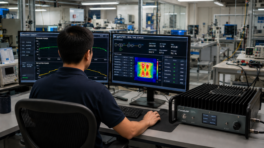
The datasheet notes real-time temperature and current monitoring, with optional forward/reverse power monitoring. In an automated lab, those values can be logged beside frequency, source power, gain setting, and test result. That kind of data is often the fastest way to explain why a test passed on Tuesday and failed on Friday.
When to Choose This Class of Amplifier
A 0.6-6 GHz 200 W GaN amplifier is a good fit when a lab needs one platform for multiple RF bands rather than a separate amplifier for every segment. It is also useful when test coverage moves across communications, aerospace control, RF interference, and measurement tasks. The 53 dB minimum gain supports many low-level RF sources, while SMA-F input and N-F output keep integration compatible with common lab hardware.
Before requesting a configuration, document frequency coverage, required field level or conducted power, waveform type, CW or modulated use, duty profile, expected mismatch, control interface, cooling plan, and whether forward/reverse power monitoring is required. A short system drawing is worth more than a long wish list.
Internal Links to Use When Publishing
Use the phrase RF power amplifier for the main CorelixRF amplifier category page if available. Link broadband RF power amplifier to the closest 0.6-6 GHz or wideband amplifier page. Link EMC amplifier or RF immunity testing to the EMC application page. Link custom RF amplifier to the RFQ or contact page. End the article with the Contact CTA.
FAQ
Can a 0.6-6 GHz amplifier be used for EMC immunity testing?
Yes, if the full RF path is designed correctly. The amplifier is one part of a system that also includes antennas or injection hardware, couplers, monitoring, calibration, and protection.
Why is gain control useful in radiated immunity work?
Gain control lets the engineer adjust delivered power while keeping the RF source in a clean and predictable range.
What should be monitored during long sweeps?
Forward power, reflected power where available, temperature, current, source level, gain setting, and alarm states are all useful.
What is the CTA?
Discuss Your RF Immunity Amplifier Setup – https://corelixrf.com/contact/