
A Ku-band BUC can look simple on a block diagram: modem IF in, RF out to the antenna. In the field, the same unit becomes a mechanical, thermal, electrical, frequency-plan, and monitoring problem. The best commissioning work is boring in the right way. The installer checks the frequency plan, confirms the reference, verifies power and weather sealing, records gain settings, and leaves behind a system that another engineer can understand six months later.
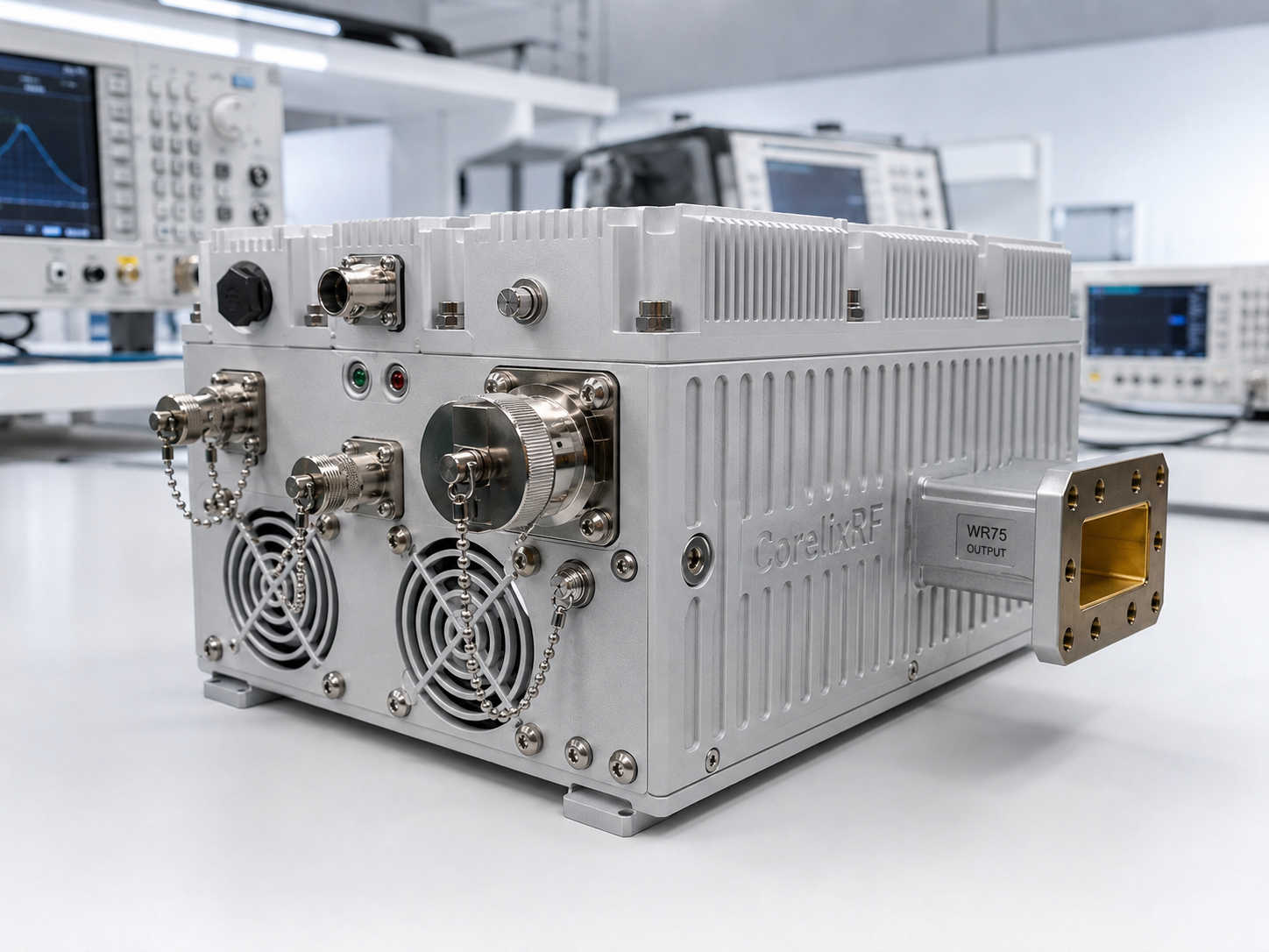
The CorelixRF CRF-BUC-Ku-100W is a GaN block upconverter platform for Ku-band satellite uplinks. It supports RF output options of 13.75 GHz to 14.5 GHz or 14 GHz to 14.5 GHz, with 100 W rated output power. IF options include 950-1450/1700 MHz or 2500-3000 MHz. The unit lists 68 dB minimum small-signal gain, 20 dB gain control in 0.5 dB steps, WR75 RF output, N-F IF input, Ethernet/RJ45 monitoring, 48 V supply over a 36-72 V range, optional AC 220 V input, IP65 packaging, 225 x 151 x 141 mm size, and 5.5 kg weight.
Commissioning Step 1: Confirm the Frequency Plan
Before mounting hardware, confirm RF range, IF range, LO plan, and reference input. The datasheet lists LO options of 12.8/13.05 GHz or 11.5 GHz and a 10 MHz reference at 0 dBm +/-5 via the IF port. A modem configuration mistake can look like a BUC problem if the installer does not write down the intended plan.
The field record should include modem IF, BUC LO, expected RF output, reference source, cable path, and whether the terminal uses 950-1450 MHz, 950-1700 MHz, or 2500-3000 MHz IF operation.
Commissioning Step 2: Inspect the Mechanical Path
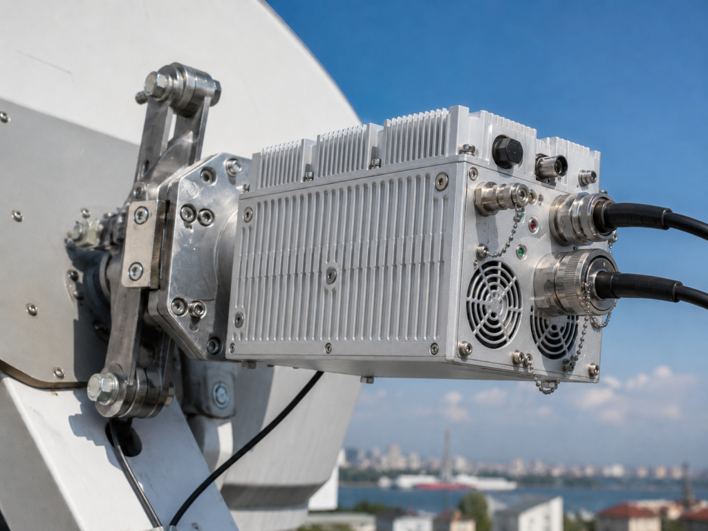
The BUC is compact, but 5.5 kg at the feed assembly still matters. Check bracket strength, vibration exposure, cable strain relief, waveguide alignment, gasket condition, and service access. For vehicle-borne and ship-borne systems, do not assume a static VSAT mounting practice will survive motion, salt air, vibration, or repeated maintenance.
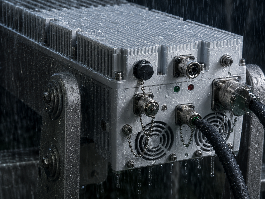
The IP65 package helps with dust and water protection, but field reliability still depends on correct connector sealing and routing. Water should not be invited to run along a cable into a connector. That one sentence has saved more terminals than many complicated checklists.
Commissioning Step 3: Verify Power Before RF
The BUC supports 48 V input over a 36-72 V range, with optional AC 220 V input, and 450 W typical power. Before enabling RF, verify supply polarity, voltage at load, cable drop, connector seating, and grounding. Mobile terminals often have power conditions that change with engine state, inverter load, or battery condition.
Commissioning Step 4: Set Gain With the Link Budget in Front of You
The unit provides 20 dB gain control in 0.5 dB steps. Do not set gain by habit. Use the link budget, modem output level, cable loss, required EIRP, and linearity margin. The datasheet lists IM3 of <=-25 dBc at 3 dB power backoff, spurious <=-55 dBc, transmit-band noise <=-76 dBm/Hz, and receive-band noise <=-156 dBm/Hz at 10.95-12.75 GHz. Those numbers are reminders that spectral quality and noise matter alongside output power.
Commissioning Step 5: Connect Monitoring to Operations
Ethernet monitoring, real-time temperature monitoring, real-time current monitoring, and alarm/fault protection should be connected to the terminal’s operating method. If the terminal is remote, mobile, or ship-borne, a local LED is not enough. The operator needs a way to know whether the BUC is hot, current-limited, muted, or faulted.
Commissioning Step 6: Record the Final State
At the end of commissioning, record RF plan, IF plan, reference level, gain setting, supply voltage, temperature, alarm state, measured output where allowed, antenna path, cable part numbers, firmware or control protocol notes, and photos of the installation. The next service visit should not start from archaeology.
Where This BUC Fits
The CRF-BUC-Ku-100W fits vehicle-borne satellite communication, ship-borne satellite communication, ground VSAT base stations, and Ku-band VSAT uplink terminals. It is strongest where a compact outdoor GaN BUC needs configurable IF/RF planning, Ethernet monitoring, IP65 packaging, and 100 W rated output.
Internal Links to Use When Publishing
Link Ku-band BUC to the CorelixRF BUC or SATCOM product page. Link satellite uplink to the SATCOM application page. Link custom SATCOM amplifier to the RFQ or contact page. Link Contact CorelixRF.
FAQ
What should be checked first during BUC commissioning?
Confirm the RF/IF frequency plan, LO selection, and 10 MHz reference before assuming any RF problem.
Why is gain setting important?
Gain affects EIRP, linearity margin, spectral quality, and link performance.
Is this BUC suitable for outdoor use?
The datasheet lists an IP65 package and -40 to +60 C operating temperature.
What is the CTA?
Contact CorelixRF About a Ku-Band Uplink BUC .
Ku-Band RF Chain Review Path
For Ku-band BUC or mobile terminal RF chain planning, compare RF power amplifier platforms, RF front-end integration planning and antenna/load interface requirements before RFQ. Send frequency range, output power, linearity, thermal margin, connector path and acceptance-document needs through the RF inquiry form.