
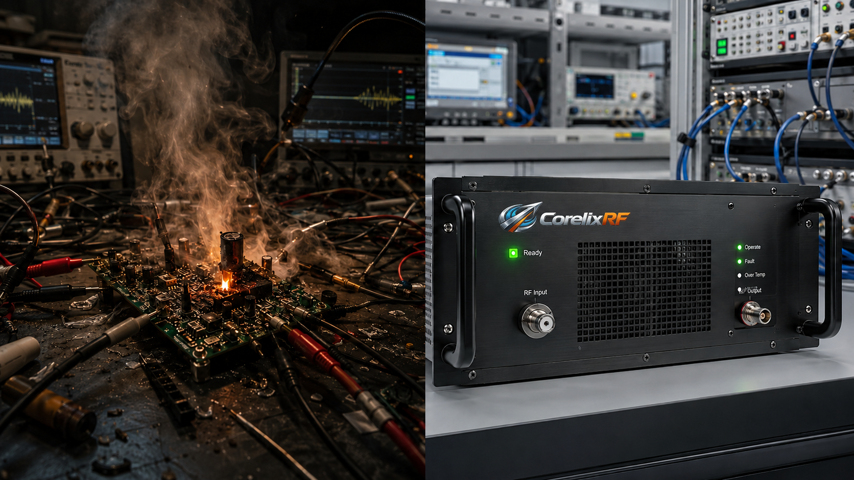
Engineers face a frustrating reality during automated radio frequency component evaluation daily. You spend weeks building Python scripts aiming at full hardware characterization. Everything looks correct within your test rack containing signal generators alongside digital multimeters. Then someone executes that automation script initiating power sequences simultaneously across all connected instruments. A loud sound emerges from your device under test immediately followed by acrid smoke filling laboratory air. Here is our reality. Your script applied a 0 dBm continuous wave stimulus directly into an unpowered amplifier input port. This specific timing error destroys internal LDMOS transistors within milliseconds before any human operator can react physically. Replacing blown components costs thousands of dollars while completely halting your product development schedule indefinitely. Such failures occur because software commands travel over LAN networks at varying speeds depending on switch latency. Your bench power supply might take fifty milliseconds stabilizing its output rail under heavy electrical load. Meanwhile, that signal generator delivers full radio frequency power almost instantly upon receiving its trigger command string. This mismatch creates a fatal condition where gate terminals experience high voltage swings without drain voltage support. Mixers and modulators also suffer similarly when subjected toward identical abusive bench conditions daily. You must treat every active component carefully regarding power application.
Boot Timing Variations
| Instrument Type | Activation Command | Typical Stabilization Delay | Risk Factor |
| Signal Generator | RF ON | < 2 ms | High |
| DC Bias Supply | Output Enable | 20 ms – 100 ms | High |
| Vector Network Analyzer | Sweep Start | 5 ms – 15 ms | Medium |
| CorelixRF Amplifier | AC Power ON | Self-Managed | Zero |
1. What Exactly Causes That Dreaded Pop During Rack Evaluations? What is our actual physical mechanism here?
Let us look inside an LDMOS die operating within radar system validation environments. These semiconductors require strict biasing protocols preventing catastrophic thermal runaway events during normal operation. When you inject a 9 kHz through 100 MHz sweep into an unbiased gate terminal directly. That high-frequency alternating current rectifies across internal parasitic diodes generating unintended massive localized currents instantly. The drain terminal sits at zero volts meaning no electron flow happens across that main channel path. All dissipated energy concentrates purely within delicate gate oxide layers melting them almost immediately upon impact. We have analyzed dozens of failed units returning from system integrator laboratories showing identical microscopic burn marks. Engineers often blame static electricity initially before realizing their automated test software contains sequencing flaws inherently. You must understand that silicon structures cannot violate basic thermodynamic laws regardless of external cooling methods applied. Air cooling fans spinning at maximum RPM provide zero protection against instant microsecond-level gate oxide rupture events. Thermal dissipation cannot happen without proper voltage potentials establishing normal electron drift velocity parameters across semiconducting channels. Your heat sinks remain cold while microscopic structures vaporize internally.
LDMOS Physical Failure Modes
| Failure Catalyst | Component Destroyed | Visible Symptom | Detection Method |
| Premature RF Drive | Gate Oxide | Melted input traces | Microscope inspection |
| Extreme Load VSWR | Drain Junction | Cracked ceramic package | VNA impedance check |
| Thermal Runaway | Gold Bonding Wires | Open circuit | DC Multimeter continuity |
| Sustained Over-drive | Active Die Area | Burned epoxy | Visual inspection |
2. Why Do Standard Python Automation Scripts Fail So Consistently?
Software developers writing test automation rarely understand microwave physics or semiconductor power sequencing requirements adequately. They send standard SCPI commands telling every rack instrument to turn on simultaneously via Gigabit Ethernet connections. Consider this hidden trap. Network packets arrive unpredictably causing jitter across instrument activation times measuring tens of milliseconds randomly. A signal generator might boot its output stage much faster than heavy industrial alternating current supplies can. That lag leaves your expensive hardware completely exposed receiving raw stimulus lacking internal protective rail voltages. We see this exact scenario frequently among electronic warfare integrators evaluating broadband modules requiring rigorous testing matrices. Their Python routines do not include hardcoded delays verifying nominal supply levels before enabling active radio transmission. Writing robust code demands polling status registers confirming all internal rails reach stable parameters prior to excitation. Failing this basic programmatic hygiene guarantees hardware destruction eventually when timing tolerances drift during long evaluation runs. Engineers deploying these automated systems must study manufacturer manuals closely identifying exact boot latency specifications for every single device. You cannot trust default software libraries managing timing gracefully without explicit manual overrides.
Script Timing Comparisons
| Script Action | Bad Practice | Professional Practice | Hardware Impact |
| Initialize Instruments | Send all commands | Sequential boot | High Risk vs Safe |
| Verify Bias | Assume OK | Poll multimeter | Blind vs Verified |
| Enable RF Drive | Immediate | 500ms Delay | Destruction vs Operation |
| Error Handling | Ignore timeouts | Halt all execution | Cascade failure vs Pause |
3. How Can You Detect Microsecond Timing Errors Using Oscilloscopes?
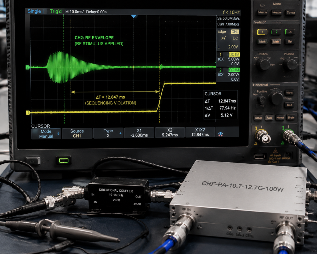
Field troubleshooting requires absolute precision capturing transient events occurring faster than human perception allows naturally. You need a high-speed digital storage oscilloscope monitoring both direct current bias rails alongside radio frequency envelopes simultaneously. Connect channel one monitoring your main supply voltage entering that device under test using standard probe attenuation. Attach channel two toward a directional coupler forward port sampling that incoming stimulus from your generator setup. Ready for our technical breakdown? Trigger your acquisition sweep acting upon that rising edge belonging to your bias voltage rail measurement. If you observe any waveform activity appearing on channel two before channel one reaches stable nominal values. You have discovered a critical sequencing violation threatening your entire hardware investment immediately during every automated cycle. System integrators building complex aviation control testing rigs must mandate these specific verification measurements during initial commissioning. Relying blindly upon instrument panel indicators masks microsecond delays responsible for sending equipment back for factory repair. Capturing these microsecond events demands triggering capabilities exceeding entry-level equipment specifications commonly found within budget constrained departments. Invest heavily into proper diagnostic tools ensuring your foundation remains solid before writing complex test matrices.
Diagnostic Oscilloscope Configuration
| Parameter | Setting | Purpose | Target Metric |
| Timebase | 5 ms / div | Capture full sequence | Millisecond resolution |
| CH1 Trigger | Rising Edge | Catch bias power-up | Start event |
| CH2 Coupling | AC 50 Ohm | Read RF envelope | Stimulus timing |
| Acquisition | Single Shot | Prevent overwriting | Clean transient view |
4. What Are Real Financial Damages When Ignoring Physical Sequencing Rules?
Blowing up an evaluation unit during mid-cycle testing creates cascading failures across your entire departmental schedule. Your engineering team loses days analyzing logs trying to determine why a seemingly perfect setup suddenly failed. Let that sink in deeply. Hardware replacement costs represent merely a fraction concerning overall financial damage inflicted upon tight project deadlines. Program managers must explain delays delaying product launches while waiting for new hardware shipments arriving weeks later. System calibration matrices require complete recalculation since new replacement modules exhibit slightly different baseline phase characteristics inherently. Furthermore, repeated unverified failures erode confidence regarding overall system architecture choices among senior technical leadership reviewing progress. Many teams mistakenly assume their chosen amplifier design lacks ruggedness instead of identifying fundamental bench timing errors. We witness communication system integrators abandoning perfectly viable technologies purely due to undiscovered software timing jitter bugs. Proper initial physical verification saves countless hours chasing phantom reliability issues across subsequent rigorous validation testing phases. Managers facing these continuous setbacks struggle maintaining team morale while investigating seemingly invisible hardware gremlins continuously. Building resilient test infrastructure requires acknowledging these physical limitations separating software ideals from hardware realities.
Financial Impact Analysis
| Incident Aspect | Direct Cost | Indirect Penalty | Total Liability Estimate |
| Module Burnout | $5000+ | Zero | $5000 |
| Calibration Loss | Zero | 24 Hours Labor | $2400 |
| Schedule Delay | Zero | Missed Deliverables | Immeasurable |
| Troubleshooting | Zero | 40 Hours Labor | $4000 |
5. How Does Our Wideband Amplifier Architecture Solve Sequencing Nightmares?
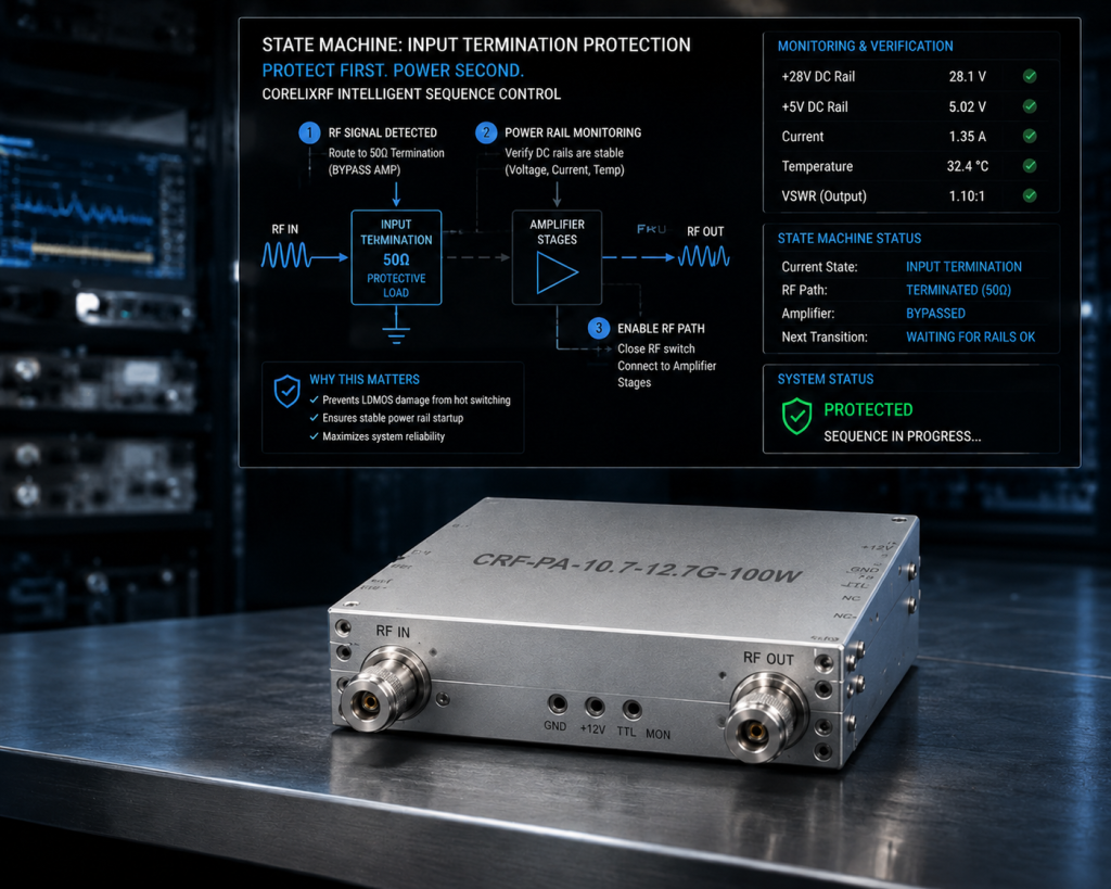
CorelixRF designed our specific architecture recognizing exactly how hostile automated laboratory environments behave under high-stress conditions. We engineered a proprietary internal state machine handling all hardware initialization completely independent from external software commands. When you apply standard AC 220V power toward this 19-inch 3U chassis using normal rack switching. This is where things get highly technical. Our internal controller physically isolates that N-Female input connector utilizing high-isolation solid-state switching matrices internally. The system monitors all internal direct current rail voltages constantly waiting for absolute stabilization across every internal node. Only after verifying perfect thermal and electrical equilibrium does our controller connect that input port toward active amplification stages. If your signal generator fires early applying 0 dBm input power prematurely during this rigorous boot sequence. That energy hits a 50-ohm internal dissipative termination completely bypassing delicate LDMOS gate structures safely and silently. This structural design guarantees your software bugs cannot translate into blown silicon under any test scenario imaginable.
Internal Boot Sequence States
| State Phase | Duration | Input Port Status | RF Output Status |
| Power Applied | 0-100 ms | Terminated 50Ω | Disabled |
| Bias Stabilization | 100-300 ms | Terminated 50Ω | Disabled |
| Fault Verification | 300-500 ms | Terminated 50Ω | Disabled |
| Active Operation | > 500 ms | Connected | Amplifying |
6. What Specific Hardware Protection Mechanisms Safeguard This Platform?
Operating between 9 kHz and 100 MHz requires extraordinary broadband matching networks handling massive multioctave bandwidths seamlessly. Our CRF-PA-9K100M-50W incorporates multiple redundant safety loops protecting against harsh realities found within electromagnetic interference testing labs. You might be wondering about specifics. We integrated lightning-fast over-drive protection circuits detecting input anomalies exceeding nominal ratings within nanoseconds physically. Simultaneously, our reverse power monitoring subsystem constantly evaluates output voltage standing wave ratios protecting against load mismatches. If someone disconnects that output N-Female cable accidentally while transmitting 50 watts continuous power outward into open space. Internal comparators instantly kill bias voltages shutting down main amplification stages preventing massive reflected energy from destroying output transistors. Furthermore, thermal sensors embedded directly within baseplate copper matrices monitor absolute operating temperatures ensuring air cooling systems maintain safe limits. These combined hardware-level features create an indestructible foundation serving demanding test measurement applications without requiring external supervision.
Built-In Protection Parameters
| Protection Type | Trigger Condition | System Response | Recovery Method |
| Over-voltage | > Nominal Limits | Auto Shutdown | Power Cycle |
| Over-temperature | Baseplate > Safe °C | Auto Shutdown | Auto upon cooling |
| Over-current | Abnormal Draw | Auto Shutdown | Power Cycle |
| VSWR Protection | Extreme Mismatch | Auto Shutdown | Correct Load |
7. How Do You Integrate This Model Into LAN Automated Benches?
Building reliable test architectures demands seamless communication bridging your host computer toward distributed rack mount instrumentation effectively. The CRF-PA-9K100M-50W features robust RS485 alongside LAN control interfaces designed explicitly for industrial automation environments. You can easily read all internal telemetry data including forward power alongside internal temperatures using standard protocol queries. Here is your integration blueprint. Your Python script should initiate AC power via smart power distribution units before polling our amplifier interface continuously. Wait until our hardware reports a ‘Ready’ status flag indicating all internal self-tests passed successfully before proceeding. Once verified, send your desired gain adjustment commands ranging up to 20 dB utilizing our digital attenuator network. Finally, command your signal generator providing stimulus knowing our hardware stands fully prepared handling dynamic broadband sweeps safely. This methodology guarantees absolute synchronization isolating your delicate device under test from unpredictable network latency variations completely.
Telemetry Data Points Available
| Parameter | Protocol | Read/Write | Function |
| Forward Power | LAN/RS485 | Read | Monitor Output |
| Reverse Power | LAN/RS485 | Read | VSWR Status |
| System Temp | LAN/RS485 | Read | Thermal Safety |
| Gain Control | LAN/RS485 | Write | Set Attenuation |
8. What Test Results Prove Reliability Across These Multioctave Bandwidths?
We subject every production unit toward agonizing environmental alongside electrical stress testing protocols exceeding standard industry requirements significantly. Our engineering team routinely injects severe power supply fluctuations simulating unstable grid conditions common across heavy manufacturing facilities. What does our data show exactly? The CRF-PA-9K100M-50W maintains a solid 47 dB nominal gain exhibiting strictly controlled flatness between -4 dB and 4 dB. Even while facing extreme 2.0:1 input VSWR conditions at maximum 0 dBm drive levels during continuous operation. Harmonic distortion remains firmly suppressed below -10 dBc while spurious emissions stay buried beneath a strict -60 dBc noise floor. Power consumption never exceeds 400 W despite delivering pure 50 W rated output power across its entire specified multioctave bandwidth. We provide comprehensive factory test pattern files supporting your specific project review requirements confirming our published mechanical alongside electrical outlines. These empirical results demonstrate why defense contractors rely heavily upon CorelixRF designs powering their most critical electronic warfare validation stations.
Table 9 RF Performance Measurements
| Specification | Minimum | Typical | Maximum | Unit |
| Frequency Range | 9 | – | 100,000 | kHz |
| Output Power | 50 | – | – | W |
| Gain Flatness | -4 | – | 4 | dB |
| Input VSWR | – | – | 2.0:1 | Ratio |
9. Why Does Physical Architecture Outperform Software Timing Solutions?
Software algorithms inherently lack absolute determinism when executing across complex general-purpose operating systems running multiple background services simultaneously. Relying purely upon Python scripts managing critical hardware switching introduces unacceptable vulnerabilities threatening delicate high-frequency components continuously. Consider our physical reality. Hardware state machines operating via dedicated microcontrollers execute internal logic paths perfectly without experiencing random CPU interrupts whatsoever. Our robust 20 kg chassis houses heavy-duty power conditioning modules rejecting incoming electrical noise before it reaches sensitive elements. Utilizing physical relays alongside solid-state switches guarantees positive isolation preventing any stray radio frequency energy from traversing inactive circuits. Software simply cannot guarantee absolute zero-voltage states across floating nodes lacking physical grounding mechanisms implemented strictly via hardware design. Investing into proper physical architecture eliminates entire categories regarding phantom troubleshooting nightmares plaguing complex system integration laboratories globally. Engineers should demand verifiable hardware-level safeguards rather than trusting arbitrary timers programmed into automated continuous integration testing pipelines.
Software vs Hardware Safeguards
| Mechanism Aspect | Software Timing | Hardware State Machine | Reliability Rating |
| Determinism | Variable | Absolute | Hardware Wins |
| Execution Speed | Milliseconds | Microseconds | Hardware Wins |
| OS Dependency | High | Zero | Hardware Wins |
| Upgrade Path | Easy via Code | Factory Set | Software Wins |
10. How Can You Upgrade Current Benches Preventing Future Transistor Burnouts?
Stop replacing destroyed evaluation modules blindly without addressing those underlying power sequencing errors destroying your hardware investments permanently. Upgrading toward intelligent amplifier architectures removes human error alongside software timing jitter from your reliability equations permanently. Take action on these engineering facts today. Review your current laboratory Python scripts verifying whether hardcoded delays exist separating bias enablement from radio frequency excitation commands. Measure your actual timing using high-speed oscilloscopes confirming those assumptions match physical reality across your entire instrumentation rack precisely. Replace aging unprotected dummy amplifiers with our CRF-PA-9K100M-50W gaining native hardware-level sequencing immunity saving massive replacement costs over time. We engineer equipment specifically surviving those brutal realities experienced daily within professional testing alongside measurement laboratories worldwide. Contact CorelixRF securing detailed mechanical integration drawings alongside comprehensive technical datasheets optimizing your next generation automated validation platform architecture today.
Research and development test benches demand rugged hardware capable of surviving software sequencing errors inherently. By implementing our CRF-PA-9K100M-50W amplifier, engineers eliminate catastrophic LDMOS failures caused by premature signal injection. Stop burning expensive modules blindly and upgrade your automated laboratory utilizing true hardware-level protection engineered for physical reality.
Frequently Asked Questions
Q1: What causes instantaneous LDMOS burnout during bench testing?
Applying radio frequency stimulus into gate terminals before drain voltage rails stabilize fully causes instant catastrophic thermal failures.
Q2: How does proper sequencing protect RF amplifiers?
Strict timing protocols ensure all internal semiconducting channels reach stable operating potentials before handling any high-frequency alternating currents safely.
Q3: Why are automated Python scripts dangerous for unverified hardware?
Network latency alongside varying instrument boot times create unpredictable timing overlaps causing premature signal injection despite perfect code structure.
Q4: What instruments detect test bench timing errors effectively?
Digital storage oscilloscopes triggering upon DC bias rails while monitoring incoming RF envelopes detect microsecond timing violations accurately.
Q5: How does the CRF-PA-9K100M-50W handle premature signal injection?
Internal state machines route incoming signals toward dissipative 50-ohm terminations until all amplification stages verify perfect electrical stabilization internally.