
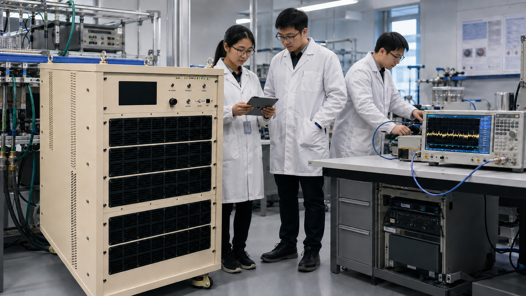
A 2-8 GHz 1000W liquid cooled RF amplifier should be specified with the facility in mind from the first review. The CorelixRF CRF-PA-2000M8000M-1000W-Liquid covers 2,000 to 8,000 MHz with 1000 W rated output power, 60 dB minimum small-signal gain, N-Female RF input, 7/16 RF output, RS485/LAN control, AC 220 V input, water cooling, and a final mechanical format to be confirmed by project drawing.
This product class fits broadband S-band and C-band test work where high CW power is needed across a wide frequency range. Search intent for this topic is usually practical: buyers want to know whether the amplifier can fit their rack, cooling plant, RF load, remote-control system, and acceptance process. The answer depends on more than wattage.
Log Entry 1: Cooling Loop Released for RF Work
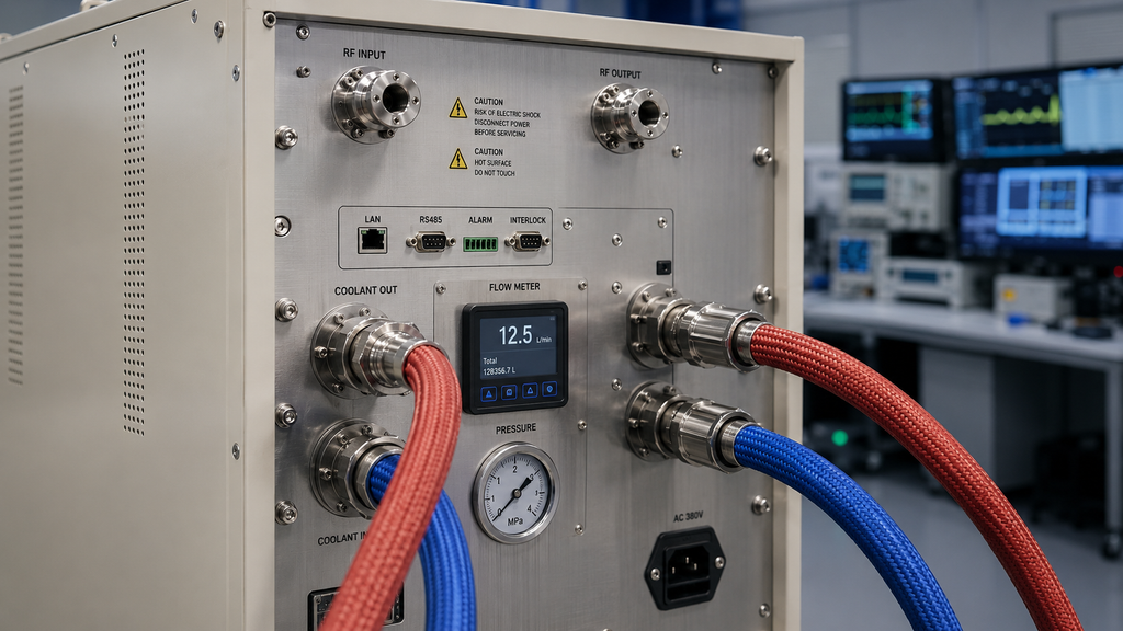
The datasheet identifies a water-cooled configuration and 0 deg C to +50 deg C operation. Before RF performance is tested, the facility should define coolant type, inlet temperature, flow rate, pressure limit, fittings, hose routing, shutoff method, leak inspection, and service access. A powerful broadband RF power amplifier can be mechanically correct yet operationally difficult if the coolant path is designed late.
The cooling loop should be considered part of the acceptance setup. First-power testing without the intended coolant condition can give misleading results. Record coolant status, amplifier temperature, current, forward power, reverse power where available, and alarm state during each test point.
Log Entry 2: Power and Load Path Signed Off
The source data lists AC 220 V +/-10%, 50/60 Hz power and 0 dBm maximum input power. That combination demands a conservative start procedure. The source generator should be locked down before PA enable, and the load path should be rated for the expected full-power condition. The output connector is listed as 7/16, so the adapter chain, directional coupler, switch matrix, and load must be reviewed at that interface.
- Confirm AC input, grounding, coolant readiness, and RF load rating.
- Set source power limits before connecting the amplifier input.
- Define calibration plane at the N-Female input and 7/16 output path.
- Record gain-control setting and remote-command state at each measurement.
- Stop testing if temperature, current, or reflected-power behavior is abnormal.
Log Entry 3: Remote Control Ownership Assigned
RS485 and LAN control are listed. Optional forward/reverse power monitoring, input power detection, GPIB programmable control, LAN remote control, and project-specific protocol support are also available by review. The buyer should decide whether remote control is only for operator convenience or whether it is part of the safety and repeatability strategy.
If the amplifier will run in an automated system, the host should log command state, gain setting, current, temperature, and fault status. Competitor content in the high-power RF amplifier space often emphasizes software control and demonstration at full power; for CorelixRF content, the safer and more useful message is to define the control and logging requirement before quotation, then validate it against the delivered configuration.
Log Entry 4: Mechanical Holds Closed
The datasheet marks mechanical form factor and dimensions as TBD. That should not be ignored. A liquid-cooled 1000 W amplifier can require hose clearance, service radius, weight handling, rear-panel planning, and space for power and RF output hardware. Ask for the final mechanical drawing before locking the rack, coolant manifold, or cable-routing plan.
If the standard configuration does not match the facility, start a custom RF amplifier review early. Customization can include control interface, protocol support, monitoring options, cooling layout, documentation, and mechanical structure, but those changes should be scoped before procurement files are finalized.
Acceptance File
The acceptance file should include the quoted model, final drawing, source power limit, output-power test points, gain flatness expectations, harmonic and spurious review, coolant settings, alarm checks, current and temperature logs, and any optional monitoring included in the order. The datasheet lists -4 dB to +4 dB small-signal gain flatness, -15 dBc harmonics, and -60 dBc spurious performance; final acceptance should use measured data for the shipped configuration.
For teams comparing CW and pulsed options, this 1000 W liquid-cooled unit is a CW broadband planning topic. If the application requires short pulses, duty-cycle definition, and timing behavior, use the pulsed RF amplifier path instead of assuming a CW platform is the right starting point.
Log Entry 5: First-Power Risk Review
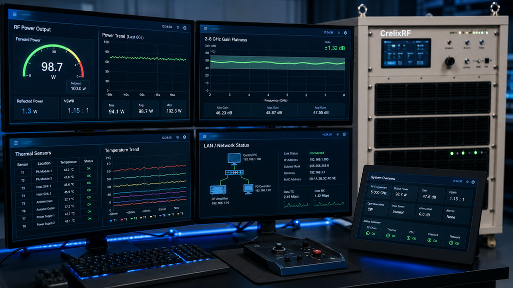
The first-power checklist should be treated as a commissioning event. The team should confirm coolant flow, AC supply, RF load, source limit, remote command state, and measurement equipment before PA enable. A 60 dB gain system can reach high output with very little input drive, so the safest test procedure is incremental and logged. Start at low drive, confirm readings, then increase only after current and temperature behavior looks normal.
Facility owners should also decide how the amplifier is removed from service if an alarm appears. The response may include disabling the RF source, removing PA enable, stopping the sweep, closing a coolant valve, or requiring manual inspection. Those steps are operational details, but they protect the amplifier and the surrounding test system.
FAQ
What frequency range and power are listed?
The model covers 2,000 to 8,000 MHz with 1000 W rated RF output power.
What cooling method is specified?
The datasheet specifies water cooling.
What RF connectors are listed?
The listed input is N-Female and the listed output is 7/16.
Why is mechanical confirmation required?
The source data marks mechanical dimensions as TBD, so final rack and coolant layout should wait for the project drawing.