
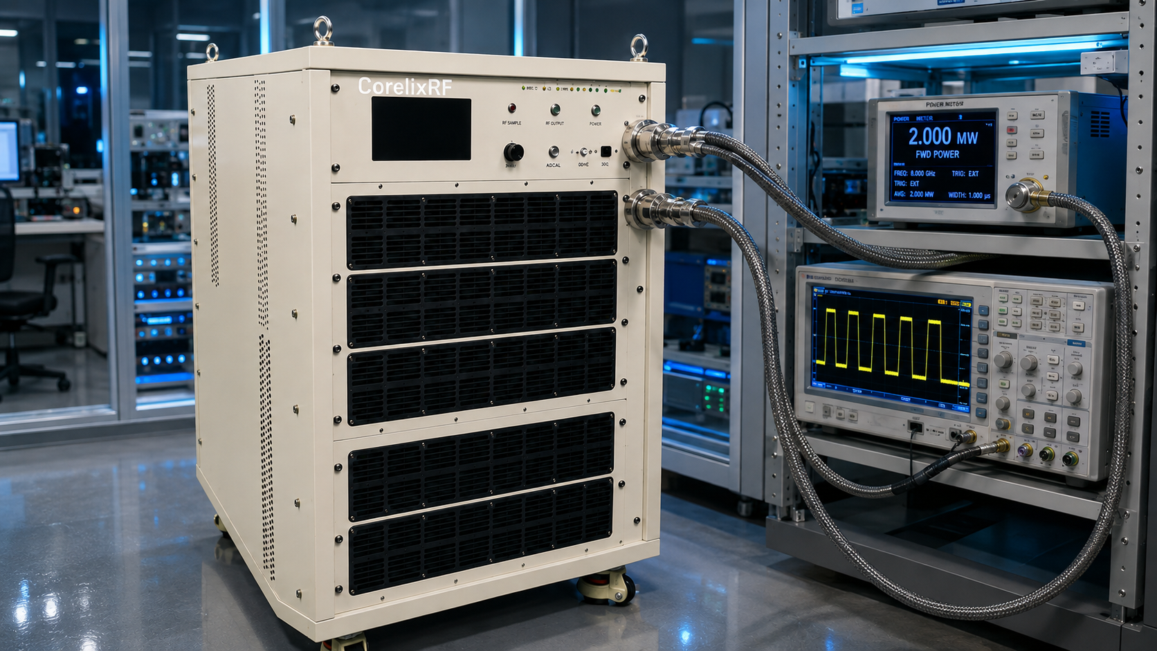
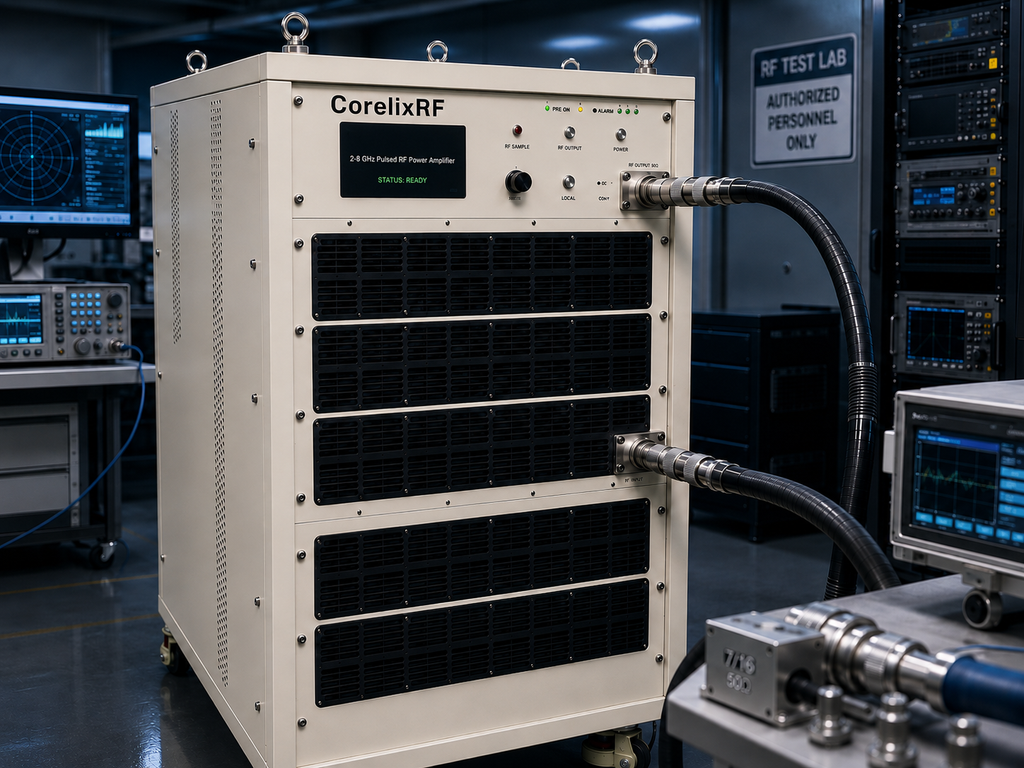
A 2-8 GHz 2000W pulsed RF amplifier is specified differently from a CW broadband amplifier. The CorelixRF CRF-PA-2000M8000M-2000W covers 2,000 to 8,000 MHz with 2000 W pulsed RF output power, 1-50 us pulse width, 10% duty cycle, 63 dB minimum small-signal gain, N-Female input, 7/16 output, RS485/LAN control, AC 220 V input, and air cooling.
The headline power number is important, but timing is what makes the RFQ credible. A pulsed amplifier buyer should define pulse width, duty cycle, repetition behavior, waveform source, trigger logic, load condition, monitoring requirement, and how the rack reacts to alarms. Without those details, the supplier cannot know whether the requested 2000 W condition reflects the real operating envelope.
SOP Phase 1: Pulse Definition
The datasheet states 1-50 us pulse width and 10% duty cycle. The RFQ should specify the exact pulse width range, expected duty condition, whether the requirement is fixed or adjustable, and whether the system needs margin for future test modes. Pulse width and duty cycle affect heat, power supply stress, measurement method, and protection behavior. They also affect how the operator interprets output power readings.
For radar-related test racks, include whether the amplifier is used for component validation, transmitter-path simulation, RF interference testing, or broader system-level evaluation. CorelixRF’s pulsed amplifier page emphasizes custom review for pulse condition, interface logic, monitoring function, and mechanical structure. That is the right framing for this model.
SOP Phase 2: Input Power Lockout
The listed maximum input power is 0 dBm, while small-signal gain is at least 63 dB. That combination requires strict source management. Do not rely on memory from a previous bench setup. Verify attenuator values, source profile, trigger state, and RF blanking before enabling the amplifier. A small input error can create a large output event.
- Confirm pulse width and duty cycle before RF drive is applied.
- Verify trigger timing and source blanking on an oscilloscope or analyzer path.
- Set input power limit at or below the datasheet maximum.
- Use a load and coupler rated for the pulsed output condition.
- Record pulse power, current, temperature, fault state, and repetition condition.
SOP Phase 3: Pulse Measurement Method
A 2000 W pulsed specification should not be measured like a 2000 W CW amplifier. The team needs an instrument chain appropriate for pulse power, pulse timing, and duty cycle. If only average power is recorded, the result may not prove that the pulse condition was achieved. If only peak power is recorded, the result may not prove that thermal and current limits are acceptable over the operating duty cycle.
This is where a high power RF amplifier acceptance file should include measurement method, sensor type, coupler calibration, pulse width, duty cycle, frequency point, input drive, gain setting, and control state. Good records reduce disputes between RF engineering, purchasing, and the end user.
SOP Phase 4: Monitoring and Fault Logging
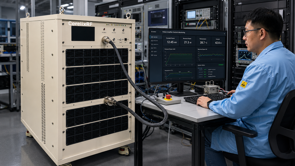
The model lists real-time temperature monitoring, real-time current monitoring, optional forward/reverse power monitoring, optional input power detection, alarm and fault protection, temperature and current alarms, and optional GPIB/LAN/project-specific protocol support. Decide before shipment which values the rack controller must read. A pulsed rack that only logs source settings and output power can miss the condition that explains a fault.
VSWR and reflected-power awareness are especially important when the output path includes switches, waveguide transitions, high-power coaxial sections, antennas, or fixtures. If forward/reverse power monitoring is needed for the test plan, include it explicitly rather than treating it as a generic amplifier feature.
SOP Phase 5: Mechanical Release
The source data marks mechanical dimensions as TBD. For a 2-8 GHz 2000 W pulsed system, this affects rack space, airflow path, cable routing, lifting, service access, and connector position. Ask for final mechanical documentation before approving a rack drawing. If the air-cooling path or output connector orientation is constrained, request review through custom RF development.
A complete RFQ should include frequency range, pulsed output power, pulse width, duty cycle, repetition behavior, source power, load condition, control interface, cooling and rack constraints, monitoring needs, and test documentation expectations. That gives CorelixRF enough information to review the real pulsed amplifier project rather than responding to a single power number.
Operator Handoff
After engineering acceptance, the operator handoff should translate the RF test file into a short daily-use procedure. It should state the allowed pulse width, duty cycle, input power limit, warmup condition, load requirement, alarm response, and shutdown sequence. That handoff is especially important when the amplifier is shared by multiple programs or when a test rack is used by both RF engineers and technicians.
The handoff should also identify which measurements prove that the amplifier is operating normally. A useful minimum set includes source power, pulse width, duty cycle, output pulse power, current, temperature, and fault status. If forward/reverse power monitoring is included, add it to the operator screen and the saved log rather than leaving it only in the engineering acceptance file.
FAQ
What pulse power is listed?
The CRF-PA-2000M8000M-2000W is listed with 2000 W pulsed RF output power.
What pulse width and duty cycle are specified?
The datasheet lists 1-50 us pulse width and 10% duty cycle.
What cooling method is listed?
The model is listed with air cooling.
What should be included in the RFQ?
Include frequency, pulse width, duty cycle, source power, load condition, control interface, cooling constraints, and documentation needs.