
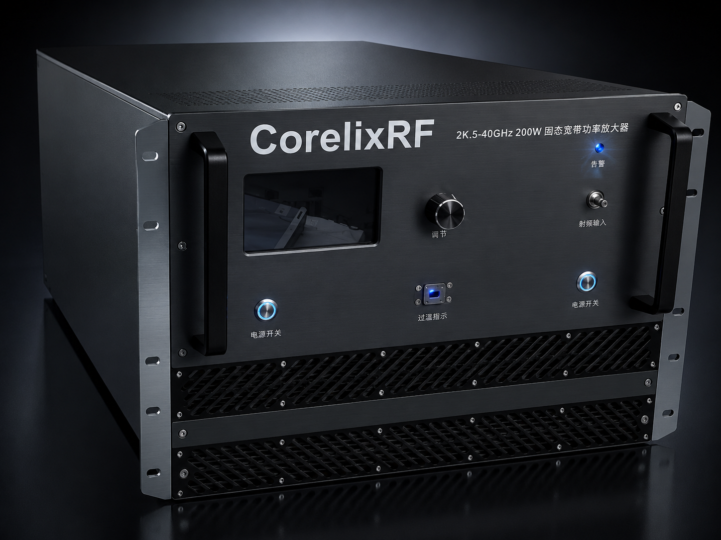
A 26.5-40 GHz 200W Ka-band power amplifier should be specified with calibration risks in mind from the start. The CorelixRF CRF-PA-26500M40000M-200W covers 26.5 GHz to 40 GHz, provides 200 W rated solid-state RF output power, uses GaN SSPA technology, and lists 53 dB minimum small-signal gain. The local datasheet identifies 2.92mm-F / WR28 RF interfaces, a forced-air 19-inch 8U rack-mount configuration, diagnostics, alarm protection, and project-ready control interfaces.
This failure-analysis article is for engineers searching for a Ka-band power amplifier, 200W mmWave amplifier, WR28 RF amplifier, high frequency power amplifier, or microwave power amplifier. The intent is to prevent measurement disputes before they occur, not to describe a failure that has already happened in a customer system.
Failure Mode 1: Unnamed Measurement Plane
The most common calibration failure is a mismatch between the requirement and the measurement plane. A buyer may ask for 200 W, while the lab measures after waveguide, adapters, couplers, or a chamber feed. The RFQ should name the acceptance plane, the instrument chain, the expected loss accounting, and the retest trigger when hardware is changed.
Failure Mode 2: Source Drive Drift
A 53 dB gain stage requires strict source control. If a test script retries at the wrong level or a source starts from a previous setting, the result can be unsafe or misleading. The acceptance method should include source limits, attenuation, RF enable sequence, interlocks, and a log tying source power to frequency, current, temperature, and output power.
- Confirm WR28 and 2.92mm-F interface state before testing.
- Use calibrated sensors and record adapter condition.
- Review airflow before running high-power sweeps.
- Capture current and temperature during every acceptance row.
- Treat VSWR, current, or temperature alarms as investigation events.
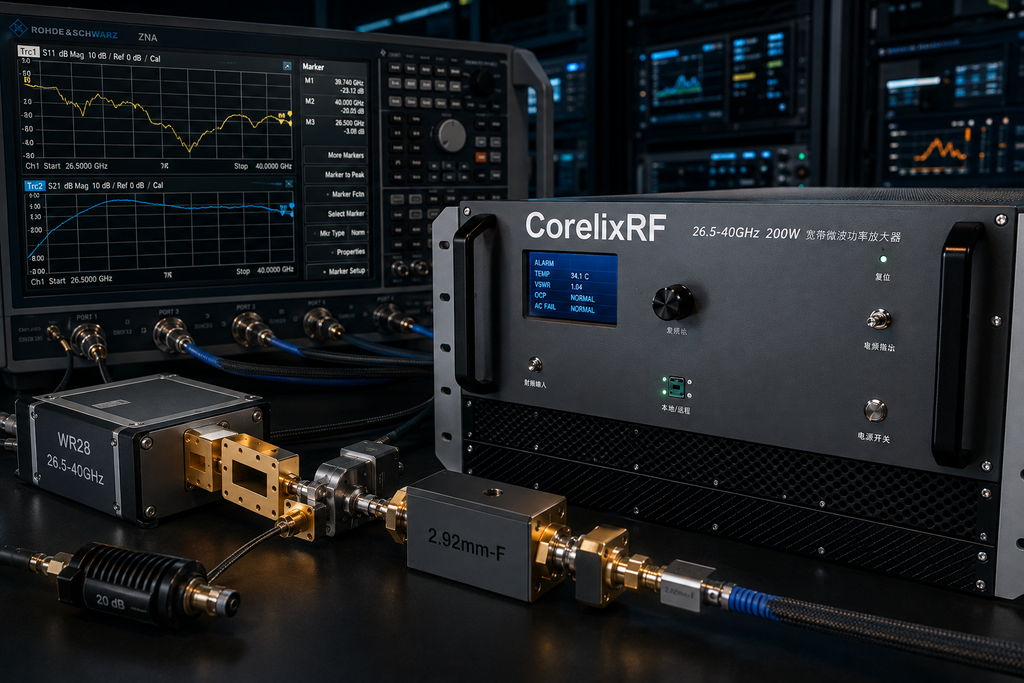
Failure Mode 3: Rack Thermal Assumptions
The source lists a forced-air 8U rack format. The rack must provide inlet clearance, exhaust space, line power planning, service access, and cable routing. If the amplifier is integrated with sources, switches, filters, or loads, CorelixRF RF integration solutions review can help define the complete rack behavior.
Failure Mode 4: Documentation Gaps
A quotation should request final mechanical drawing, test data, and control protocol where applicable. When documentation is requested late, the receiving team may not get the format needed for internal signoff. The engineering and manufacturing path is relevant when acceptance evidence must match a formal project process.
Corrective RFQ Structure
A corrective RFQ states operating band, output power target, waveform, duty condition, source drive, interface plan, rack environment, cooling assumptions, control method, monitoring needs, alarm response, and documentation format. If a different mechanical or control package is required, use custom RF development rather than assuming the standard rack covers every project variable.
The keyword set is 26.5-40 GHz 200W Ka-band power amplifier, Ka-band power amplifier, 200W mmWave amplifier, WR28 RF amplifier, and high frequency power amplifier. These phrases fit high-intent searches from engineers preparing a serious Ka-band acceptance plan.
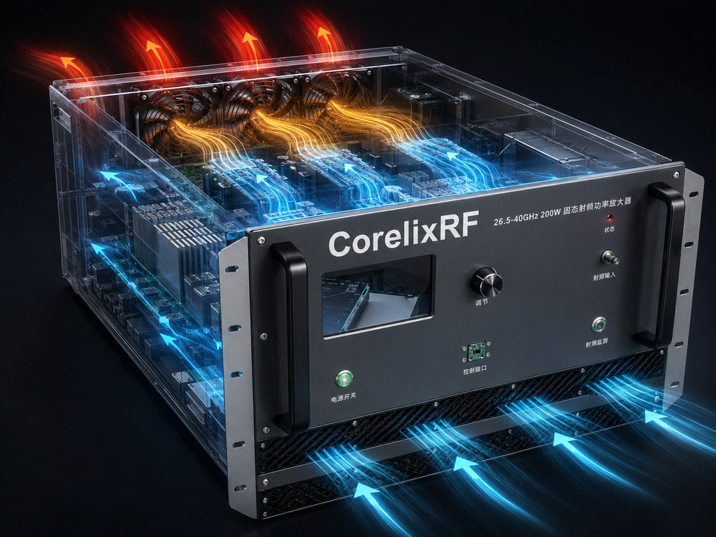
Analysis Closeout
The safe public message is narrow and useful: the datasheet supports frequency, rated power, gain, interface, rack, cooling, monitoring, and protection details. Final system behavior depends on the source, load, waveguide path, airflow, controls, and measurement method. That boundary makes the article credible for technical buyers.
Use the failure-analysis format as a pre-purchase checklist. If each failure mode has an owner and evidence field, procurement can compare amplifier options without reducing the decision to frequency and wattage alone.
Prevention Record for High-Power Ka-Band Work
A prevention record should be created before the first acceptance run. It should name the RF source, maximum drive level, waveguide assembly, load rating, sensor model, rack airflow condition, warm-up rule, alarm response, and retest trigger. The record does not need to be long. It needs to be clear enough that another engineer can repeat the same measurement without guessing the hidden setup assumptions.
For a 200W mmWave amplifier, the receiving team should also define what changes require engineering review. Examples include replacing a waveguide section, changing the load, moving the rack, updating control software, or altering airflow. These are not unusual maintenance events, but they can change the context of a calibration result. A failure-analysis article can therefore help buyers plan the evidence package before they order the amplifier.
The content remains grounded in public technical facts: band, output power, gain, interface, rack format, cooling, diagnostics, and protection. It does not promise delivered power at an unnamed plane, compliance success, or immediate availability.
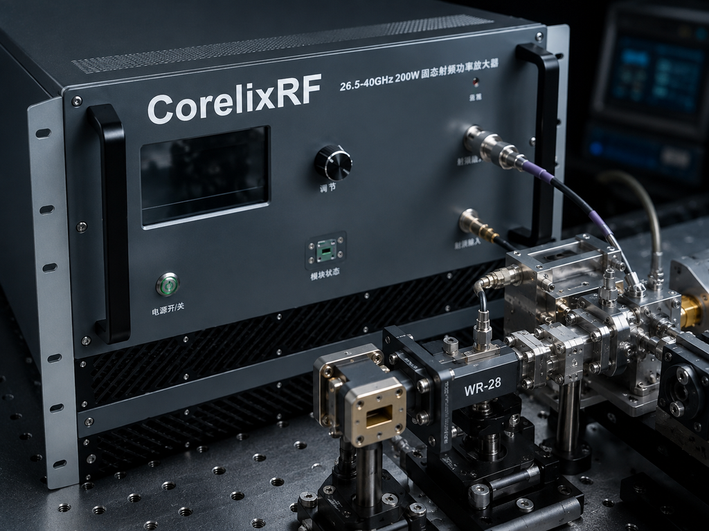
How to Write the Acceptance Request
The acceptance request should ask for the exact data the receiving lab needs, including frequency points, output power measurement method, gain condition, thermal condition, control state, and alarm behavior. If the internal quality process requires a specific report layout, that should be named in the RFQ. High-power Ka-band systems create enough integration variables that documentation format should not be treated as an afterthought.
This makes the article useful for search users who already understand the product category. They are not looking for a generic answer to what an amplifier does. They are trying to prevent calibration failure, power-plane confusion, and late-stage rack changes before committing to a 26.5-40 GHz system.
FAQ
What frequency range does CRF-PA-26500M40000M-200W cover?
The local datasheet lists 26.5 GHz to 40 GHz.
What output power and gain are listed?
The source lists 200 W rated output power and 53 dB minimum small-signal gain.
What RF interfaces are listed?
The datasheet identifies 2.92mm-F / WR28 RF interfaces.
What rack format is listed?
The source lists a forced-air 19-inch 8U rack-mount configuration.