
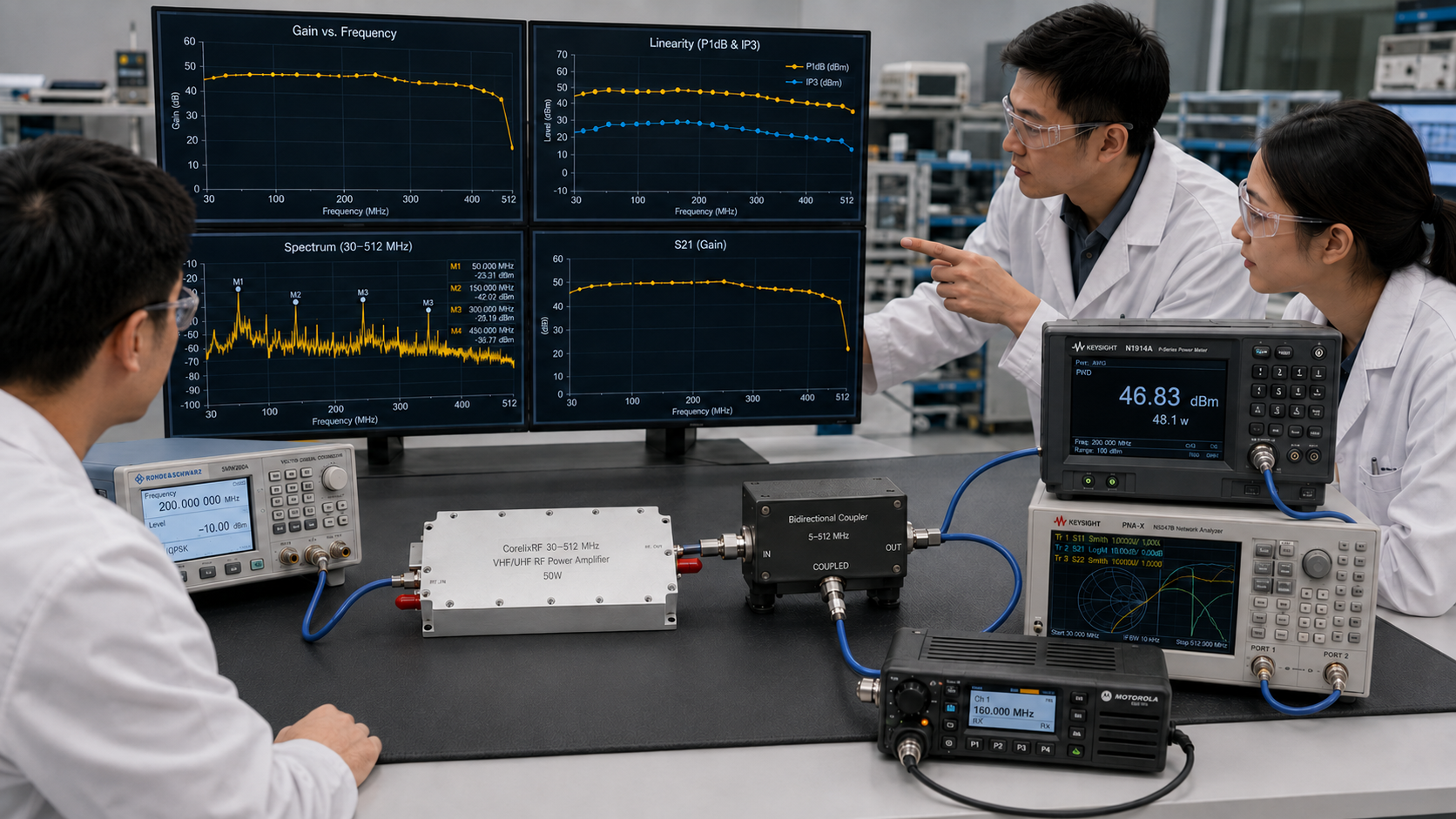
A 30-512 MHz VHF/UHF RF power amplifier serves a different engineering need than microwave or SDR-only amplifier content. This frequency range is relevant when a project must cover low-band RF testing, VHF/UHF communication links, EMC pre-compliance, radiated immunity setups, broadband laboratory work, or OEM low-band transmit chains. Instead of emphasizing wide microwave coverage, the main selection question is whether the amplifier can provide practical RF output across a lower-frequency band while fitting the project’s power class, cooling method, load condition, and documentation requirements.
CorelixRF publishes a 30-512 MHz VHF/UHF RF amplifier platform with 30 W, 50 W, 100 W, 150 W, and 200 W standard power classes. The public page describes the platform as a 28 VDC, air-cooled module design for EMC testing, VHF/UHF communication test benches, broadband RF chains, and OEM low-band RF system integration. Detailed RF data, measured curves, current consumption, VSWR reference, and mechanical drawings are provided after project requirement review, which is appropriate because low-band RF systems can vary widely in duty mode, antenna/load condition, cable route, and integration space.
Why This Article Is About EMC and Low-Band RF, Not Microwave Testing
The search intent for a 30-512 MHz amplifier is usually very different from the search intent for a 2-6 GHz or 18-40 GHz amplifier. Engineers and purchasing teams searching this band may be preparing an EMC test bench, validating VHF/UHF radios, driving a broadband antenna, reviewing a 50 ohm load path, or building an OEM RF subsystem. They usually care less about mmWave waveguide decisions and more about power class, antenna mismatch, duty cycle, field-strength planning, load protection, and mechanical integration.
For EMC use, the amplifier must be reviewed together with the antenna, chamber or open-area test setup, cable loss, coupler, directional power measurement, and expected field strength. For communication benches, the important items are often source level, modulation condition, output filtering, antenna match, and repeatability. CorelixRF’s 30-512 MHz RF amplifier page is the most relevant internal link because it frames the platform around these lower-frequency applications.
Power Class Selection: 30W to 200W
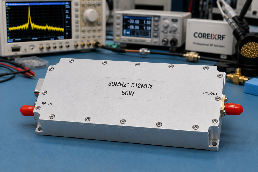
The public model table lists CRF-PA-30M512M-30W, 50W, 100W, 150W, and 200W power classes. A 30 W or 50 W unit may fit lab evaluation, lower-power VHF/UHF benches, or EMC pre-compliance work where the required field level is moderate. A 100 W class may be more appropriate for RF test benches and OEM integration. Higher 150 W and 200 W classes should be reviewed when the test path needs more RF output, wider margin, or broadband system validation.
The best class should be selected from the required output at the load or antenna, not only the amplifier nameplate. Cable loss, coupler insertion loss, antenna gain, test distance, mismatch, and operating mode can all change the effective output condition. If the test plan includes long cables or broadband antennas with variable VSWR, the engineering review should include those details before final model recommendation.
Typical RF Chain for 30-512 MHz
A practical 30-512 MHz chain usually starts with a signal generator or SDR source, then a driver stage or gain plan, the CorelixRF VHF/UHF PA, output filtering or a coupler, and finally an antenna, dummy load, DUT, or chamber path. Each stage can change the amplifier requirement. The input drive level must be compatible with the amplifier’s gain plan. The output-side path must handle power safely across the required band. The measurement setup must account for cable and coupling loss.
CorelixRF’s RF front-end platform page is useful here because it treats SDR/source, amplifier, and output-side condition as one reviewed RF chain. That approach is especially relevant for VHF/UHF projects where antennas, field-strength targets, and load conditions can dominate the real performance.
When to Request Custom Sub-Band Review
Not every project needs full 30-512 MHz coverage. CorelixRF publicly lists custom sub-band review examples such as 30-88 MHz, 100-400 MHz, 225-400 MHz, and 400-512 MHz. A custom sub-band review can be useful when the project has a narrower operating range, special connector or mechanical layout, project-defined thermal design, custom frequency band, or OEM integration requirement.
This is also where buyers should avoid forcing a catalog model into a system that needs documented integration work. If the amplifier must fit a specific enclosure, communicate with a host controller, meet a defined airflow path, or operate with a known antenna/load configuration, the requirement should be submitted before quotation. The Contact CorelixRF page is the correct CTA target for that review.
FAQ
What is the focus keyword for this article?
The focus keyword is 30-512 MHz VHF/UHF RF power amplifier.
Is this platform suitable for EMC testing?
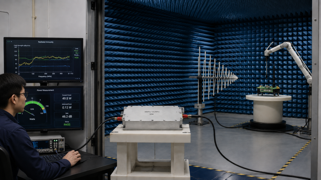
It can be reviewed for EMC test benches and pre-compliance setups where stable VHF/UHF RF output is required. Final selection should consider antenna gain, cable loss, duty cycle, load condition, and required field strength.
Which power classes are publicly listed?
CorelixRF lists 30 W, 50 W, 100 W, 150 W, and 200 W standard platform power classes for the 30-512 MHz series.
Can the amplifier be optimized for a narrower band?
Yes. CorelixRF states that custom sub-band review is available when full 30-512 MHz coverage is not required.
What should I send for engineering review?
Send frequency range, output power, operating mode, input signal level, supply voltage, cooling method, antenna or load condition, connector requirement, quantity, and project stage.