
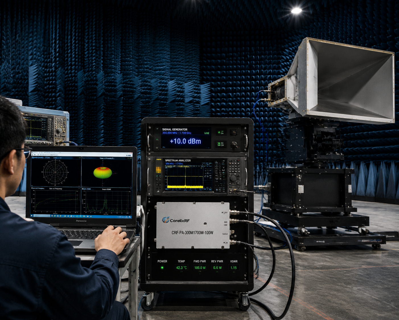
The CRF-PA-300M1700M-100W is a useful model to evaluate when an engineering team needs a 100 W broadband RF power stage across 300-1700 MHz. This range can support multi-band communication testing, UAV-related RF integration, SDR-linked transmit chains, antenna characterization, and OEM platforms that require more coverage than a narrowband amplifier can provide.
CorelixRF lists the CRF-PA-300M1700M-100W on its 300-1700 MHz RF power amplifier platform page:
300-1700mhz.
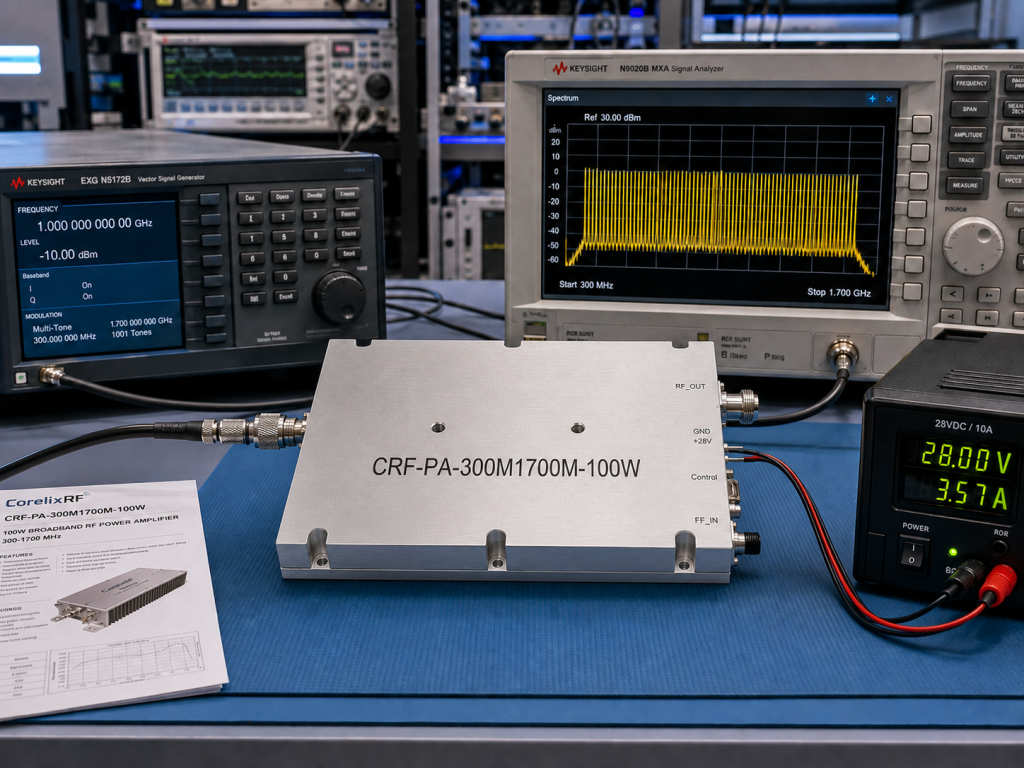
The public specification table identifies it as a 300-1700 MHz, 100 W model with 50 +/- 1 dB typical gain, input VSWR of 1.8 or better, 28 VDC supply, and a 200 x 158 x 25 mm mechanical class. Those numbers make it a more specific article topic than a general broadband amplifier guide, while still staying inside public CorelixRF product data.
Why This Model Is Different From Lower-Power 300-1700 MHz Options
Within the same 300-1700 MHz series, CorelixRF also lists 30 W and 50 W models in smaller 125 x 59 x 21.5 mm formats. The CRF-PA-300M1700M-100W steps into a higher-power class and a larger mechanical outline. That matters for buyers because the decision is no longer only about whether the band is right. The system must also support the current draw, heat path, mounting area, cable routing, and airflow expected from a 100 W broadband PA.
For bench use, the 100 W class can provide practical power margin without moving immediately into the 150 W or 200 W options. For OEM integration, it gives engineers a defined middle point between compact evaluation modules and higher-power system hardware.
Where a 300-1700 MHz 100W Amplifier Fits
The 300-1700 MHz band is attractive for teams working across UHF and L-band-adjacent ranges. A single 300-1700 MHz amplifier can reduce model switching in a test platform, especially when the project includes several frequency windows. That can simplify fixture planning, software-controlled testing, and incoming inspection because the same amplifier family can be reviewed across a broad span.
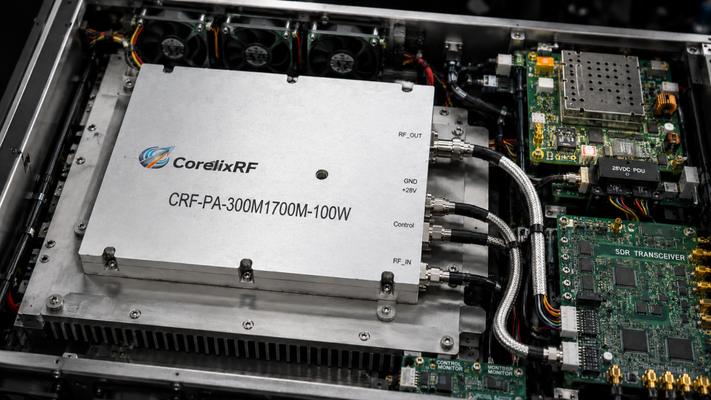
Typical fit areas include communication test platforms, broadband RF transmit chains, antenna and component evaluation, UAV-related RF integration, and multi-band laboratory setups. If the project requires even wider coverage, the 300-2700 MHz RF amplifier page may be worth comparing:
300-2700mhz.
If the project needs microwave operation above 2 GHz, the 2-6 GHz RF power amplifier series may be a better fit:2-6ghz.
Drive Level, Gain, and Chain Planning
CorelixRF lists 50 +/- 1 dB typical gain for the CRF-PA-300M1700M-100W. That is useful for signal-chain planning because it helps engineers estimate required input drive, driver-stage needs, and attenuation strategy. The amplifier should be reviewed with the actual source, not as an isolated module.
If the source is an SDR, signal generator, exciter, or driver amplifier, measure available output across the operating band and confirm whether the amplifier is expected to operate in a linear, compressed, or saturated condition. CorelixRF notes that typical input drive for rated output is confirmed under datasheet test conditions, so buyers should request model-specific drive margin during RFQ.
Thermal and Mechanical Fit
The public model table places the CRF-PA-300M1700M-100W in a 200 x 158 x 25 mm format. That footprint should be checked before chassis design, especially when airflow, connector bend radius, and mounting access are constrained. CorelixRF emphasizes mechanical drawing packages, connector references, and thermal integration guidance for this series.
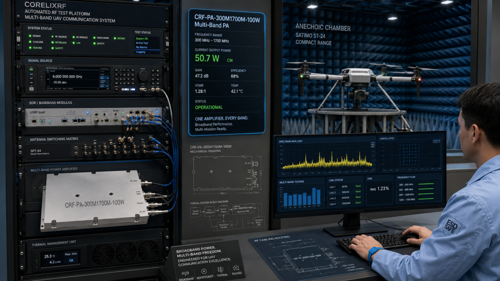
The model uses the broader series’ air-cooled solid-state platform. Air cooling can simplify integration, but it still requires a defined airflow path and enough thermal headroom for the intended duty cycle. Teams should share duty cycle, ambient temperature, enclosure layout, mounting orientation, and operating duration during the first review.
Documentation to Request
For an internal approval package, request the CRF-PA-300M1700M-100W datasheet, mechanical drawing, gain/frequency curve, output power data, input VSWR data, and sample unit test report format. CorelixRF’s page states that shipment test records covering gain, output power, and input VSWR are available by project scope, which is valuable for incoming inspection and supplier qualification.
Internal Links for Related Review
If this model is close but not exact, compare it with the CRF-PA-300M1700M series, the broader RF power amplifier overview, CorelixRF’s RF testing and validation page, the SDR and RF signal generation application page, and custom RF development for sub-band optimization.
FAQ
What is the CRF-PA-300M1700M-100W used for?
It is suited to 300-1700 MHz broadband RF testing, multi-band communication platforms, UAV-related RF integration, antenna evaluation, and OEM RF systems that need a 100 W power class.
What public specifications are available?
CorelixRF publicly lists 300-1700 MHz frequency coverage, 100 W output power, 50 +/- 1 dB typical gain, input VSWR of 1.8 or better, 28 VDC supply, and a 200 x 158 x 25 mm size class.
Should I choose 100W instead of 150W or 200W?
Choose the power class after reviewing output requirement, duty cycle, PSU capacity, airflow, enclosure size, and load condition. The 100 W model can be a balanced option when the project does not require the higher classes.
Can this model be optimized for a narrower band?
CorelixRF states that custom frequency subsets can be reviewed for flatter gain and better efficiency within a target operating range.
Request an RF Amplifier Review