
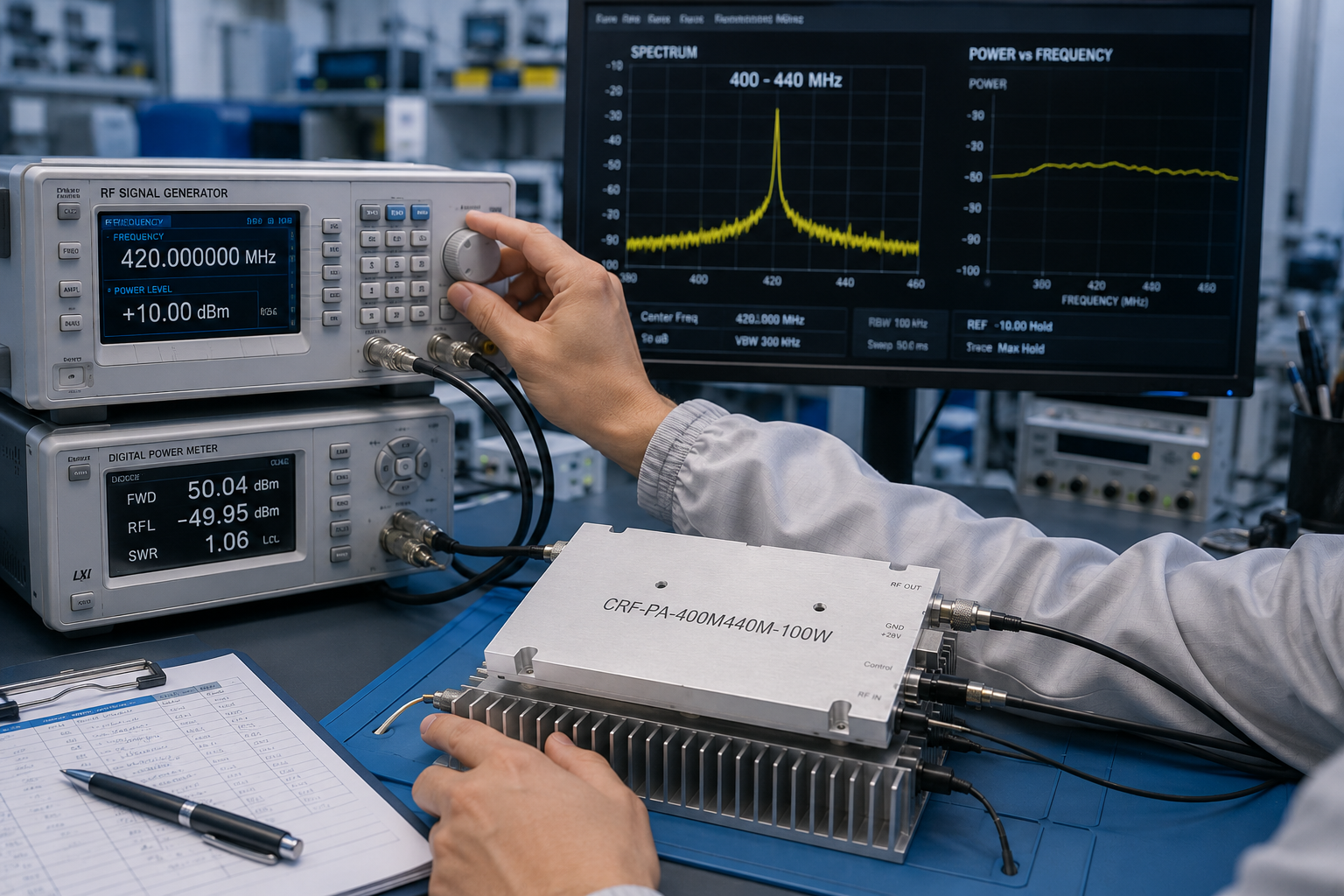
Purpose: this lab SOP describes how an engineering team can accept the CorelixRF CRF-PA-400M440M-100W as a 400-440 MHz UHF RF amplifier for communication test benches. The goal is to confirm that the amplifier, fixture, cooling, control wiring, and measurement chain are ready for use. It is not written as a buyer’s guide. It is written as a practical sequence that a lab can follow before releasing the amplifier into repeatable testing.
Scope
The SOP applies to the CRF-PA-400M440M-100W, a GaN SSPA covering 400-440 MHz with 100 W rated CW output power and 80 W minimum output power. The datasheet lists 46 dB minimum gain, 48 dB typical gain, 50 dB maximum gain, and a 20 dB gain adjustment range with 0.5 dB step information. It is relevant to communication systems, RF test and measurement systems, narrowband RF system amplification, and fixed-band system integration.
Required Bench Conditions
- Stable +28 VDC nominal supply with current limit set below the maximum test threshold.
- Rated 50 ohm load, calibrated coupler, and power meter suitable for the expected output power.
- Known RF source level and attenuation plan.
- Mounted external heat sink and airflow available before RF drive is applied.
- D-Sub 15-pin control and power wiring checked against the project pinout.
This model sits within CorelixRF’s broader UHF RF power amplifier topic area, but the lab should not use a broad-band test assumption. The acceptance points should be inside the 400-440 MHz operating window, with the lower, middle, and upper parts of the band documented.
Procedure A: Pre-Power Inspection
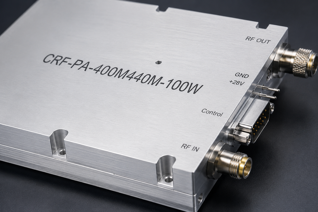
Inspect the RF connectors, DC wiring, control connector, heat-sink contact, and load path. The datasheet lists SMA-KFD46 RF connectors, a 160 x 120 x 25 mm mechanical size, approximate 1.4 kg weight, and external heat-sink cooling. Do not apply RF input before confirming that the load is connected and the cooling path is active. Record the ambient temperature and the fixture identifier in the test note.
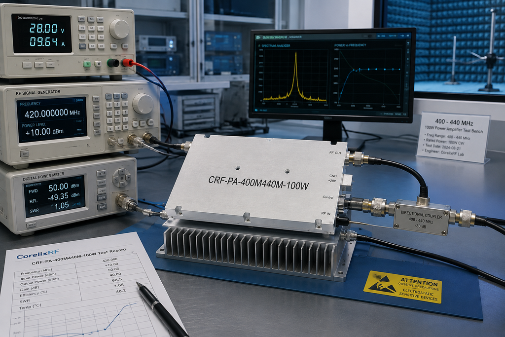
Procedure B: Low-Drive Bring-Up
Power the DC supply first, keep the RF source disabled, enable the PA, and then raise input drive gradually. PA enable/disable time is listed up to 100 microseconds, so automated benches should avoid ambiguous timing. Monitor current while increasing drive. The listed current is 16 A typical and 20 A maximum, with a 24-32 V operating voltage range.
Procedure C: RF Output and Gain Check
Measure output power and gain at representative points in the 400-440 MHz band. The acceptance form should include source level, cable loss, attenuator value, measured output, calculated gain, and heat-sink condition. If the bench needs coverage outside this fixed band, compare the setup with a 300-2700 MHz RF power amplifier before approving the UHF fixture for broader use.
Procedure D: Protection and Monitoring Review
Protection functions listed for this model include over-temperature shutdown and recovery, over-VSWR locked shutdown, over-voltage lock above 32 V, and over-current lock above 22 A. Optional RS485 monitoring/control, forward and reverse power indicators, and temperature analog output are also listed. Confirm the safe method for checking alarms before intentionally forcing any abnormal state. Some protection behavior may need to be reviewed with CorelixRF before test.
Pass/Fail Release Criteria
Pass the amplifier only when the output target, gain behavior, current draw, thermal response, control timing, and fault reporting match the agreed test condition. Fail or hold the release if the test fixture is unstable, the heat sink is not final, the RF source level is uncertain, or the fault response has not been documented. For special packaging or control changes, move the requirement to custom RF amplifier review.
Data Recording Template
For each acceptance run, record the date, operator, fixture ID, amplifier serial number, source frequency, source level, gain setting, measured output power, DC voltage, current draw, heat-sink temperature, load type, and any alarm state. The purpose is not to create a long report. It is to make later troubleshooting possible. If output changes after the amplifier is installed in another bench, this record helps determine whether the amplifier changed or the fixture changed.
The lab should also keep a controlled startup and shutdown script. Startup begins with cooling and load confirmation, then DC supply, then PA enable, then RF drive. Shutdown removes RF drive first, then disables the PA, then removes DC power after the test state is stable. This order reduces operator variation and protects the amplifier from avoidable sequencing mistakes during repeated communication-system tests.
The SOP should include a hold point after the first low-power RF output appears. At that moment, verify that current draw, measured gain, heat-sink temperature, and monitoring values are reasonable before increasing drive. This hold point catches wiring, calibration, and load mistakes early. It also gives the operator a repeatable pause in the procedure instead of relying on judgment while power is already rising. If the hold point fails, stop the procedure and preserve the readings before changing the bench setup.
FAQ
Why test lower, middle, and upper band points?
Those points show whether the amplifier and fixture behave consistently across the 400-440 MHz operating window.
What output power should be checked?
The datasheet lists 100 W rated CW output power and 80 W minimum output power.
What cooling method is listed?
The model uses external heat-sink cooling.
Why use an SOP format for this article?
An SOP format helps lab teams convert amplifier specifications into repeatable acceptance steps.