
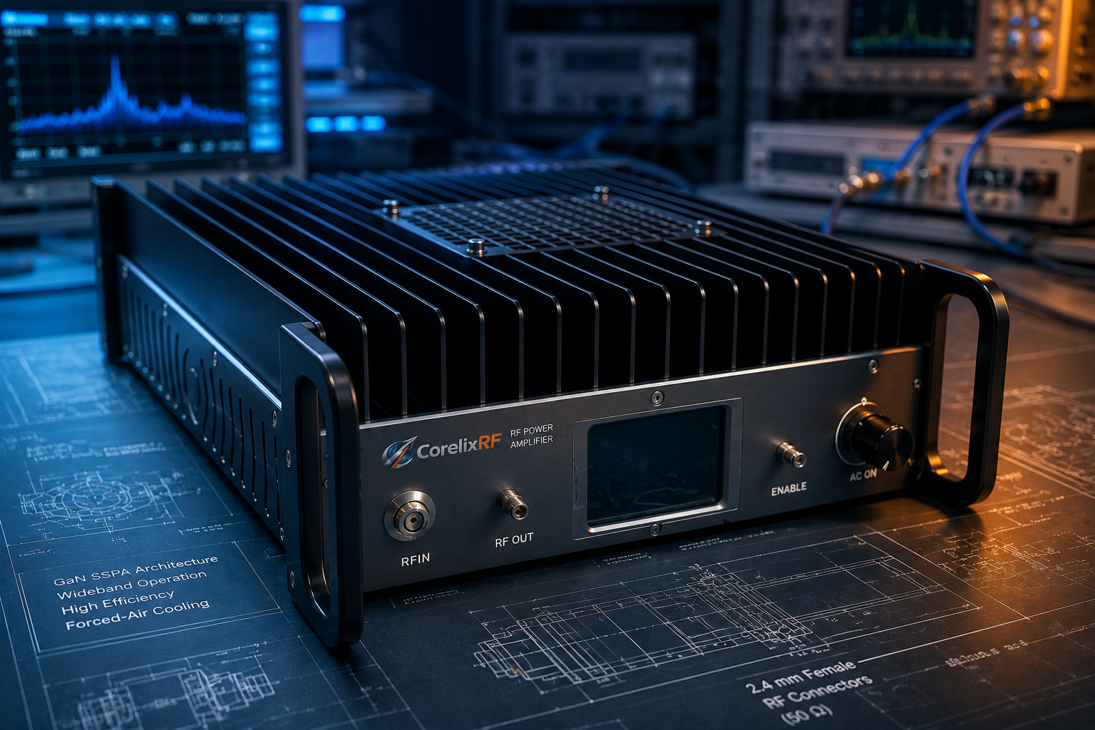
Notebook entry: the CorelixRF CRF-PA-18000M46000M-5W should be handled like a field integration component, not a casual benchtop accessory. It covers 18-46 GHz with 5 W rated output power, 40 dB minimum small-signal gain, and a GaN SSPA architecture. The frequency range alone tells the team that connector handling, calibration planes, cooling, and control wiring will shape the final measurement as much as the amplifier itself.
Observation 1: The First Risk Is Usually Mechanical
The datasheet lists 2.4 mm female RF input and output connectors. In the field, that detail changes the work. A 2.4 mm interface requires correct torque, clean mating surfaces, high-quality adapters, and disciplined storage. If a worn adapter is installed between the source and the amplifier, a measured output issue may be blamed on the amplifier even when the root cause is connector repeatability. For buyers comparing CorelixRF millimeter wave amplifier platforms, the connector plan should appear in the RFQ.
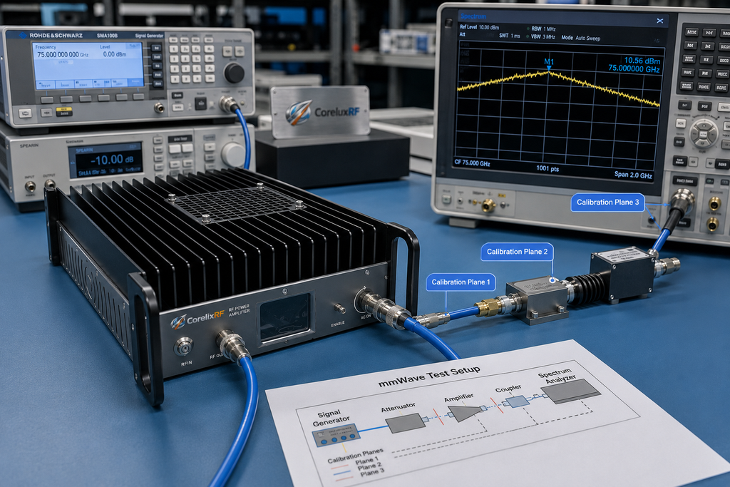
Observation 2: Wideband Output Needs a Calibration Story
The model spans 18 GHz to 46 GHz, which is wider than many single-band mmWave test cases. The datasheet lists small-signal gain flatness from -8 dB to +8 dB and up to 15 dB gain control range. A useful field note separates full-band behavior from application-band behavior. Full-band sweeps show broad amplifier character. Application-band checks show whether the actual system has enough output margin, stable gain, and acceptable thermal behavior at the frequencies that matter.
Observation 3: It Is Not the Same Decision as an 18-40 GHz Unit
Some projects only need the more common 18-40 GHz window, and CorelixRF provides an 18-40 GHz RF amplifier platform for that discussion. The CRF-PA-18000M46000M-5W is more relevant when the upper extension to 46 GHz is useful. The field engineer should ask whether the added frequency span is a real requirement or only a hedge against future scope creep.
Observation 4: Cooling Is a System Behavior
The amplifier uses forced-air cooling and is listed for 0 deg C to +50 deg C operation. Forced air means the final installation must protect inlet and exhaust paths. It also means rack neighbors can affect the amplifier if they dump heat into the same airflow channel. Real-time temperature monitoring and real-time current monitoring are listed, with optional forward/reverse power monitoring and optional input power detection. Use those signals during integration, not only after a fault.
Observation 5: Alarms Should Have a Written Response
Protection functions include alarm and fault protection, over-temperature protection, over-drive protection, over-voltage protection, and VSWR protection and alarm functions. In a field notebook, the important entry is not just that protection exists. The important entry is what the host rack does next. The control plan should define whether RF drive is removed, whether the PA is disabled, whether the event is logged, and who can restart the test.
Field Handover Checklist
- Document the calibration plane and adapter stack.
- Record the expected input level and gain setting.
- Confirm forced-air direction and rack clearance.
- Record RS485 control details and alarm behavior.
- State whether the project needs standard model support or custom RF amplifier review.
The field integration mindset prevents vague troubleshooting. If a later measurement changes, the team can compare connector stack, calibration plane, source level, cooling condition, and alarm history before assuming the amplifier has changed. That is especially important for a broadband microwave power amplifier operating across mmWave frequencies.
Notebook Entry: What Changed Since the Last Good Test?
When an 18-46 GHz measurement changes, the first field question should be practical: what changed since the last good test? Check whether the adapter stack changed, whether a cable was bent more tightly, whether the source level was recalibrated, whether the gain setting moved, whether cooling airflow was blocked, or whether the control software cleared an alarm without recording it. This method prevents the team from blaming the amplifier before the surrounding mmWave setup is checked.
The notebook should preserve the approved setup in words even when the article itself contains no images. Record the connector sequence, calibration plane, torque practice, source sweep range, power meter configuration, and ambient condition. A compact 5 W mmWave amplifier can be reliable and repeatable, but only when the handling process is repeatable. At 46 GHz, informal setup habits become measurement variables.
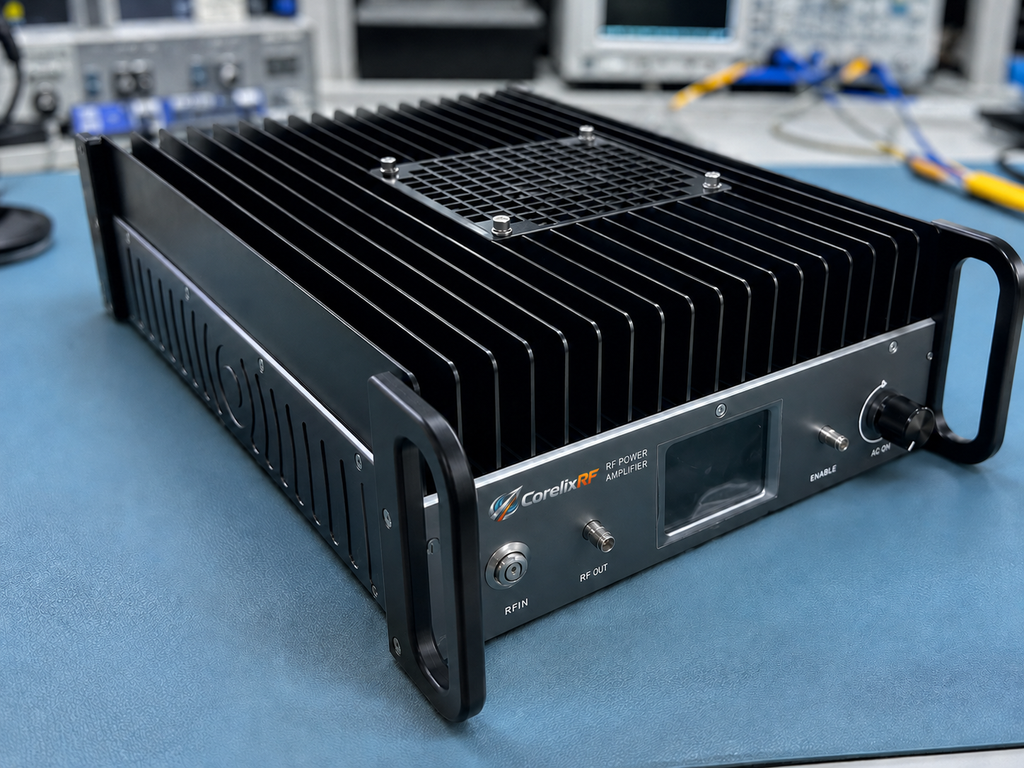
The field note should also separate transport handling from operating behavior. A small mmWave unit may move between benches, chambers, racks, or customer demonstrations. Each move can change connector condition, cable bend radius, and airflow access. Recording the physical move and the first post-move check gives engineers a clean history when comparing results across locations or after a long storage period. The same note should identify who last mated the connectors and whether any adapter was replaced. If the unit returns from another lab, repeat the low-power verification before any full-output sweep. This keeps the notebook useful when multiple engineers share the same hardware. It also shortens future fault isolation.
FAQ
Why use a field notebook format?
The notebook format emphasizes connector handling, calibration, cooling, and alarm behavior during real integration work.
What output power is listed?
The CRF-PA-18000M46000M-5W is listed for 5 W rated output power.
What RF connectors are used?
The datasheet lists 2.4 mm female input and output connectors.
Why is calibration important?
At 18-46 GHz, adapters, cables, and calibration plane changes can strongly affect measured output.