
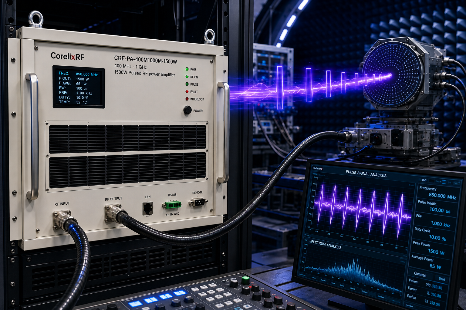
A pulsed RF power amplifier in the 400 MHz-1 GHz range is normally reviewed when a project needs high peak RF output under defined pulse timing rather than continuous-wave operation. CorelixRF CRF-PA-400M1000M-1500W is specified for 400-1,000 MHz operation with 1500 W rated pulsed output power, 1-50 us typical pulse width, 5% duty cycle, 62 dB minimum gain, N-Female RF input/output, RS485 / LAN control, and forced-air 6U rack integration.
This article is written for engineering and purchasing teams comparing a UHF and L-band amplifier path where peak power, pulse timing, load protection, and mechanical integration all need to be reviewed before purchase.
Why Pulse Conditions Define the Amplifier Choice
Pulse amplifiers are selected by a combination of frequency, peak power, pulse width, duty cycle, repetition behavior, and thermal design. A 1500 W number is only meaningful when the pulse condition is defined. The CRF-PA-400M1000M-1500W datasheet lists 1-50 us typical pulse width and 5% duty cycle, so any request outside those conditions should be sent for project review.
The lower microwave and upper UHF range also makes the load path important. At 400 MHz-1 GHz, cables, N-type connectors, couplers, filters, antennas, and dummy loads must be checked for the expected peak and average power. CorelixRF’s RF amplifier platform direction emphasizes frequency, power, waveform, interface, cooling, and validation requirements rather than a simple catalog purchase.
How Engineers Should Review This Pulsed RF Amplifier
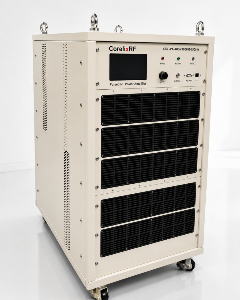
Start by separating peak power from average thermal load. The amplifier is a pulsed SSPA, so the system designer should document the intended pulse width, duty cycle, and pulse repetition behavior. If the project requires longer pulses, higher duty cycle, or unusual timing, the thermal and protection margin must be reviewed before the model is specified.
The datasheet lists 62 dB minimum gain, ±3 dB gain flatness, and 5 dBm maximum input power. That means source drive should be measured during integration. Do not assume a signal generator setting equals the input level at the amplifier connector after cables, switches, attenuators, and protection hardware.
Confirm peak power, pulse width, and duty cycle together
For this model, confirm 1500 W pulsed output against the actual frequencies and pulse timing used in the system. If acceptance testing requires specific points across 400-1,000 MHz, include those points in the RFQ.
Review the RF interface and load path early
N-Female input and output simplify many high-power RF paths, but the complete load chain still needs review. Connector heating, mismatch behavior, reflected power, coupler directivity, cable rating, and grounding should be checked before the rack layout is frozen.
Treat cooling and facility requirements as RF requirements
The 6U rack-mount format and forced-air cooling should be treated as part of the RF design. Leave airflow clearance, define ambient temperature, and confirm service access.
Integration Notes for Test, Radar Simulation, and RF System Validation
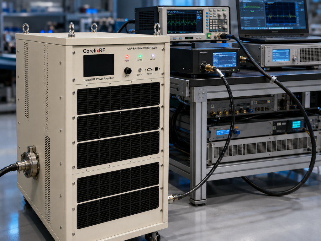
This amplifier can be reviewed for laboratory RF pulse testing, communication system validation, and controlled system-level RF work where the project is authorized and the load environment is known.
For an OEM rack or automated test bench, RS485 / LAN control, optional GPIB, and optional monitoring functions should be mapped into the control software and fault handling sequence.
Control, monitoring, and protection planning
Protection planning should include overdrive behavior, load mismatch response, alarm handling, and whether forward/reverse power monitoring is required. These decisions affect both equipment safety and data quality.
RFQ details to prepare before requesting a recommendation
Before asking for a quote, provide frequency range, target peak output power, pulse width, duty cycle, pulse repetition behavior, input drive level, connector preference, load VSWR, cooling method, control interface, monitoring requirements, mechanical envelope, and required acceptance documents. CorelixRF’s RF amplifier RFQ checklist is the practical place to turn these points into a review package.
Where This Model Fits in CorelixRF’s Pulsed Platform Path
This model extends CorelixRF’s public pulsed RF amplifier platform direction below the common 1.0-3.2 GHz listed range and should be reviewed as a project-specific high-power pulse path.
If the requirement is closer to 1-2 GHz or S-band, CorelixRF can compare related pulsed platforms through Contact CorelixRF.
FAQ
Is CRF-PA-400M1000M-1500W a pulsed RF power amplifier?
Yes. The local datasheet identifies it as a solid-state pulsed RF power amplifier and lists model-specific pulse width and duty cycle conditions.
Can the pulse width or duty cycle be changed?
Pulse conditions are project-sensitive. The datasheet values should be treated as the supplied configuration baseline; any different pulse width, duty cycle, timing behavior, or thermal margin should be reviewed with CorelixRF before quotation.
What information matters most for a pulsed amplifier RFQ?
Frequency, peak output power, pulse width, duty cycle, pulse repetition behavior, source drive level, load VSWR, cooling method, control interface, and acceptance test points matter more than a single wattage number.
Does this article claim stock, certification, or customer results?
No. It only uses the local CorelixRF datasheet and public CorelixRF platform direction. Stock, lead time, compliance documentation, and project test data must be confirmed directly by CorelixRF.
Where should buyers send requirements?
Use the CorelixRF Contact page and include frequency, pulse condition, power, coolin