
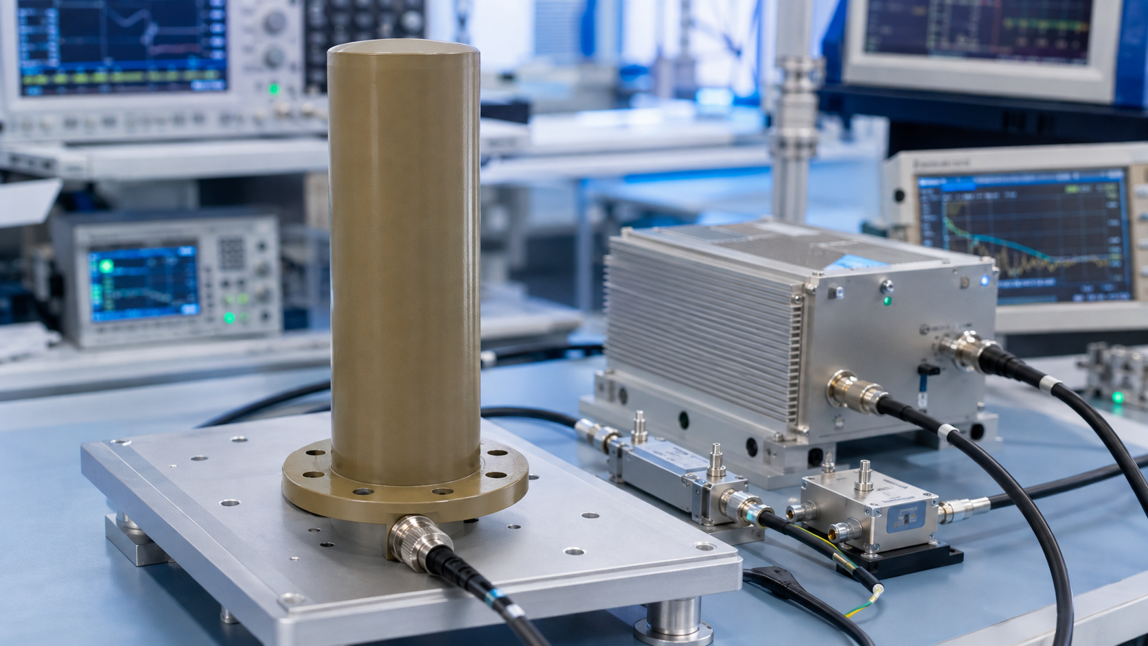
A 400 MHz to 6 GHz omnidirectional antenna should be selected as part of the complete RF path, not as an isolated mechanical accessory. The antenna affects delivered field strength, pattern coverage, mismatch risk, mounting load, cable routing, and the protection margin required by the connected transmitter or amplifier. CorelixRF CRF-OA-400M6000M-0-9dBi is specified as a Omnidirectional Antenna covering 400 to 6,000 MHz, with 0 to 9 dBi gain, 250 W maximum power handling, and N-J bottom connector.
For buyers planning a CorelixRF RF system, the useful question is whether the antenna supports the installation target with enough margin and enough documentation. Frequency range, gain, VSWR, polarization, radome material, connector placement, and mounting details should all be reviewed before finalizing the RF chain.
Start With Coverage and Installation Geometry
The 400 to 6,000 MHz band can be used in many fixed communication, test, and system-integration environments. The antenna choice should begin with the actual coverage problem. Engineers should define whether the system needs directional gain toward a known sector, broader site coverage, or a controlled test path between known points. A omnidirectional antenna such as CRF-OA-400M6000M-0-9dBi is useful when those requirements match the listed radiation behavior and installation constraints.
The datasheet lists vertical polarization, VSWR below 2.0 in a 50 ohm system, and a 50 ohm system. These values should be reviewed with the transmitter, feed cable, lightning protection, filters, and any power amplifier in the path. CorelixRF also has related guidance on antenna-path protection during mismatch events, which is relevant whenever the antenna is connected to a high-power RF front end.
Published Specifications for CRF-OA-400M6000M-0-9dBi
The product data lists 400 to 6,000 MHz frequency coverage and 0 to 9 dBi gain. Power handling is listed as 250 W maximum power handling. The RF interface is N-J bottom connector. Mechanical data lists diameter 90 x 240 mm with a 145 mm flange and about 1 kg. The antenna uses copper element with nylon radome, and the connector is placed at the bottom for installation planning.
The specified temperature range is -40 to +65 C operating temperature and -40 to +80 C storage temperature. That range matters for outdoor and fixed installations where heat, cold, solar exposure, wind loading, and service access can affect long-term reliability. Because antenna performance is tied to its environment, the RFQ should include mounting height, nearby structures, enclosure or mast details, cable length, and any environmental assumptions.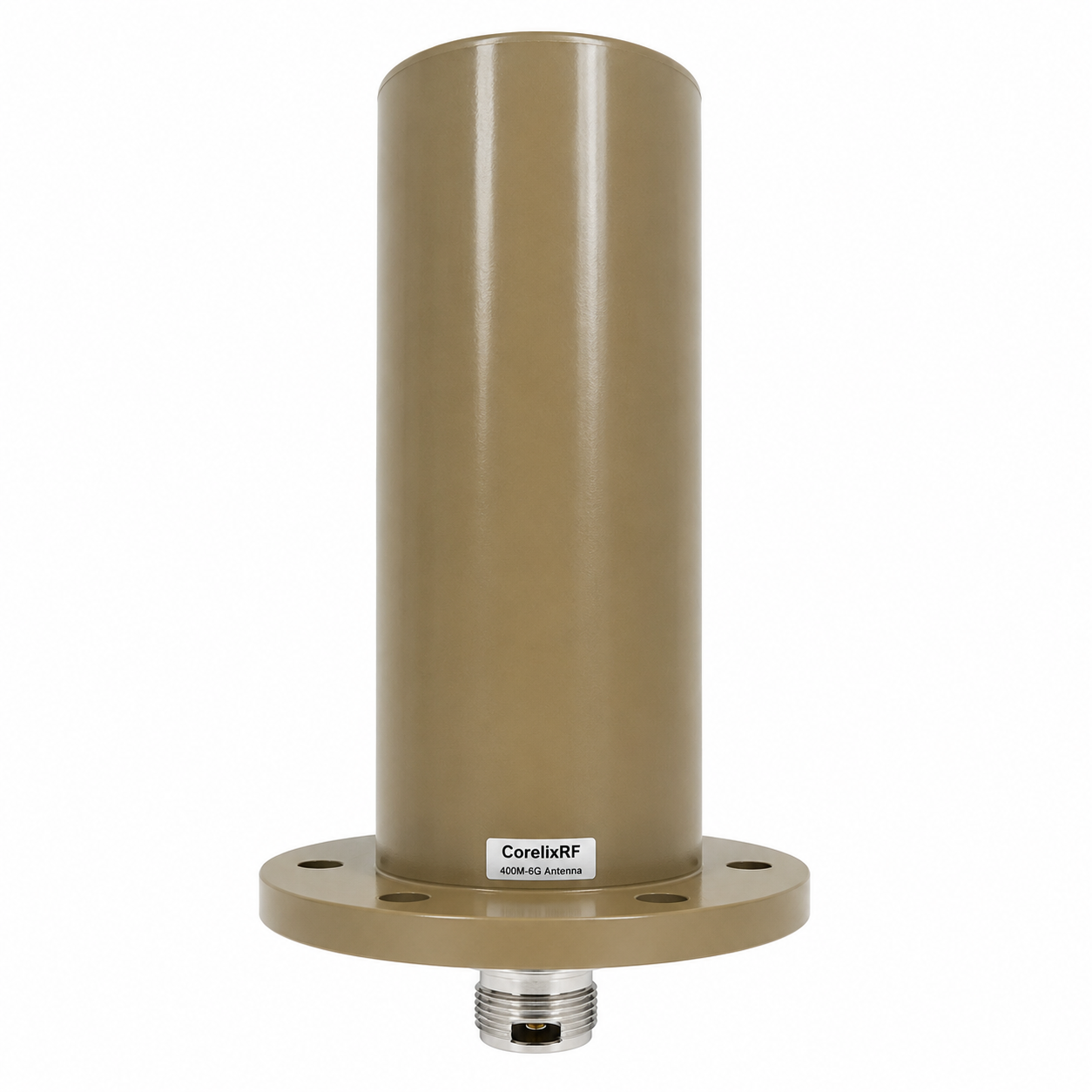
VSWR, Power Handling, and RF Chain Risk
Antenna mismatch does not only affect coverage; it can also increase reflected power into the upstream equipment. The listed VSWR below 2.0 gives a baseline for planning, but the actual installed performance can change with nearby metal, brackets, cable strain, water ingress, or incorrect mounting. If the antenna is paired with a high-power amplifier, the final system should include appropriate monitoring and protection behavior.
For teams using the antenna in a test setup, the acceptance point should be explicit. It may be VSWR at the antenna connector, field strength at a test location, received power at a measurement antenna, or a complete communication-link result. The RF acceptance criteria should be written before installation so the buyer and supplier agree on what evidence is needed.
Mechanical and Mounting Review
The mounting note for this model is flange mount for outdoor, fixed installation, or system integration. Mechanical details should be reviewed together with cable bend radius, sealing method, connector access, radome clearance, and maintenance needs. A small difference in mounting hardware can change the installation schedule, especially when the antenna is mounted outdoors or integrated into a fixed platform.
Because the product uses copper element with nylon radome, the buyer should confirm whether the standard configuration fits the environmental and mechanical requirements. If a different connector, radome detail, color, cable option, or mounting structure is needed, those items should be listed in the request instead of assumed after quotation.
RFQ Checklist for Antenna Projects
A practical RFQ for CRF-OA-400M6000M-0-9dBi should include frequency band, desired coverage direction, mounting method, maximum RF power, connector type, cable plan, environmental range, installation location, documentation needs, and any pattern or VSWR evidence required for review. If the antenna will be used with an amplifier, include amplifier output power, protection behavior, and the expected duty condition.
CorelixRF can review custom connector, mounting, radome, and integration details where applicable. Procurement teams can also use a structured RFQ checklist to avoid late changes around mounting, interface, or documentation requirements.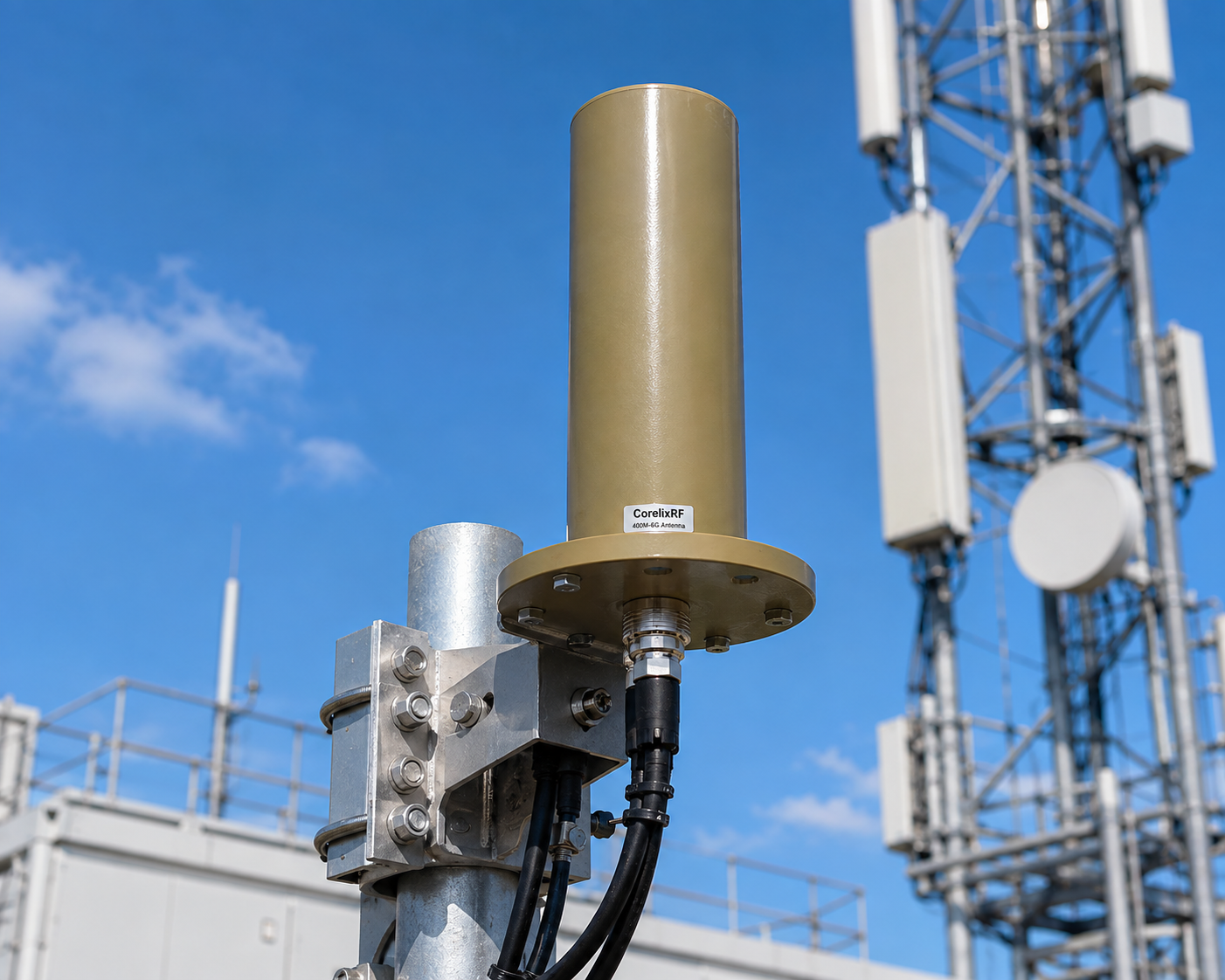
Planning Broadband Coverage With One Antenna
A broadband omnidirectional antenna is useful when the system must support several operating bands from one fixed location, but the RF team should still review gain variation and pattern behavior across the full range. Cable loss, mounting height, nearby structures, and transmitter power can affect each band differently. For that reason, acceptance should include the frequencies that matter most to the actual project, not only a single mid-band check.
FAQ
What frequency range does CRF-OA-400M6000M-0-9dBi cover?
The datasheet lists 400 to 6,000 MHz frequency coverage.
What gain is specified?
The listed gain is 0 to 9 dBi. Final system coverage still depends on installation geometry, cable loss, mounting height, and nearby structures.
What connector does the antenna use?
The datasheet lists N-J bottom connector, with bottom connector placement.
What polarization is specified?
The antenna is specified with vertical polarization.
What should I send for a project review?
Send the frequency band, power level, coverage target, mounting method, connector needs, environmental conditions, cable plan, and required test evidence.