
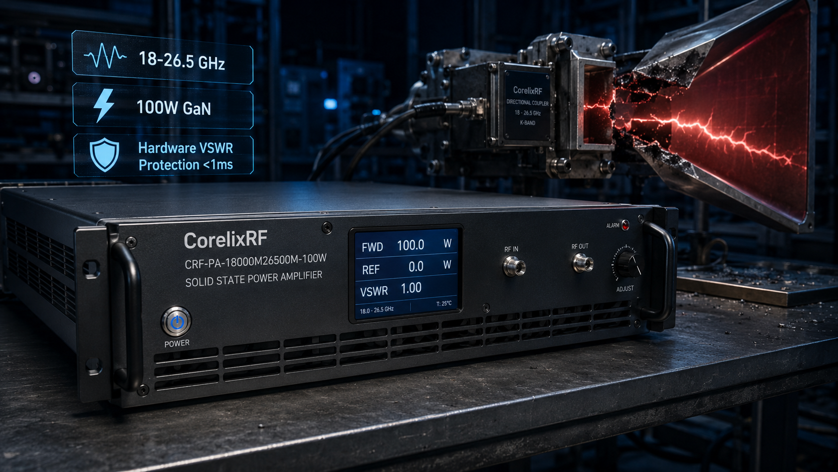
Hidden Faults in Radar Frequency-Hopping Environments: Software Polling VSWR Delay Leads to Instant Amplifier Burnout Upon Antenna Breakage. Radar installations often face a hidden danger when hardware fractures occur during active operations. Software polling methods check reverse power states too slowly. A shattered feedhorn reflects massive energy back down your transmission line instantly. You lose an expensive RF module within milliseconds. Operations halt completely. Hardware-level analog protection loops bypass software latency entirely. Operating our manufacturing facility for thirty years has taught our engineering team that analog detection saves hardware. Here’s the deal: physical reality always outpaces digital scheduling.
1. What causes structural failures in high-frequency radar antennas?
Vibration fatigue
Salt fog embrittlement
Mechanical shock
Radar installations endure brutal physical realities daily. Tracked armored vehicles transfer severe mechanical shock directly through chassis mounts into waveguide assemblies. High-frequency vibration fatigue degrades metal joints over thousands of operational hours. Coastal deployments introduce another aggressive factor. Salt fog embrittlement attacks exposed flanges relentlessly. This environmental degradation compromises structural integrity silently. A seemingly minor impact can fracture a weakened feedhorn instantly. When physical breakage occurs, transmission lines suddenly terminate into open circuits. You might be wondering: how does this impact upstream electronics? Total reflection of transmitted energy happens within nanoseconds. We measure these catastrophic events using fast transient oscilloscopes. Our field data shows structural failures peak during rapid turret movements. This physical reality requires robust upstream defense mechanisms. Designing systems for thirty years proves that mechanical weaknesses always expose electronic vulnerabilities.
2. Why do traditional software polling VSWR protections fail here?
Polling interval lag
Frequency-hopping speed mismatch
Thermal cascade
Digital microprocessors handle system diagnostics using scheduled interrupt cycles. Software polling intervals typically range between 50 and 100 milliseconds. Radar frequency-hopping sequences operate at vastly faster speeds. A transmitter might shift bands hundreds of times per second. When an antenna fractures, maximum reflected energy travels back instantly. The software protection routine remains asleep waiting for its next scheduled check. What’s the real story? That delay allows full forward power collision with reflected waves. Gallium Nitride transistors experience extreme voltage standing wave spikes immediately. This delay triggers an irreversible thermal cascade inside semiconductor junctions. Software simply acts too slowly for high-speed microwave phenomena. We need deterministic analog responses instead of scheduled digital inquiries. Our factory floor engineers witness this mismatch repeatedly when evaluating third-party integrated systems.
Comparison of VSWR Protection Response Times
| Protection Type | Typical Response Time | Mechanism | Failure Risk |
| Software Polling | 50 – 100 ms | Digital Interrupts | Critical during fast hops |
| Analog Hardware | < 1 ms | Direct Comparator | Negligible |
3. How does VSWR mismatch physically destroy gallium nitride (GaN) transistors?
Reflected power mechanics
Voltage standing wave spikes
Gate-drain breakdown
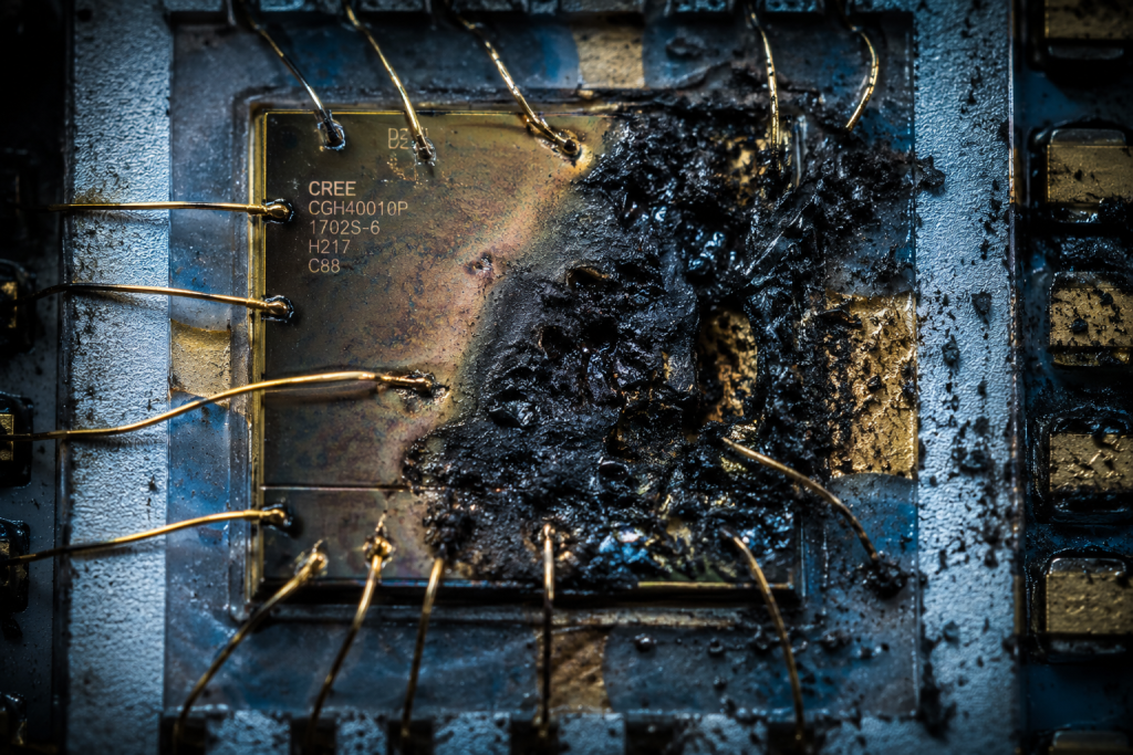
Broken antennas create severe impedance mismatches instantly. Forward RF waves collide with returning reflected waves inside your transmission line. This collision generates massive voltage standing wave spikes along amplifier output stages. GaN devices handle impressive power densities under normal 50-ohm conditions. However, extreme voltage peaks exceed critical gate-drain breakdown thresholds rapidly. This is where it gets interesting: the destruction happens at a microscopic level. Dielectric layers punch through due to intense localized electric fields. Catastrophic thermal events melt transistor bonding wires fractions of a second later. You will find charred remnants upon opening failed modules. Physical engineering dictates that voltage limits remain absolute boundaries. We cannot cheat basic electromagnetic principles using clever software algorithms. Every burned component tells a story of unmatched physics overriding digital commands.
4. What are the frontline diagnostic steps for detecting polling delay faults?
Fast oscilloscope triggering
Directional coupler setup
Reading transient reflections
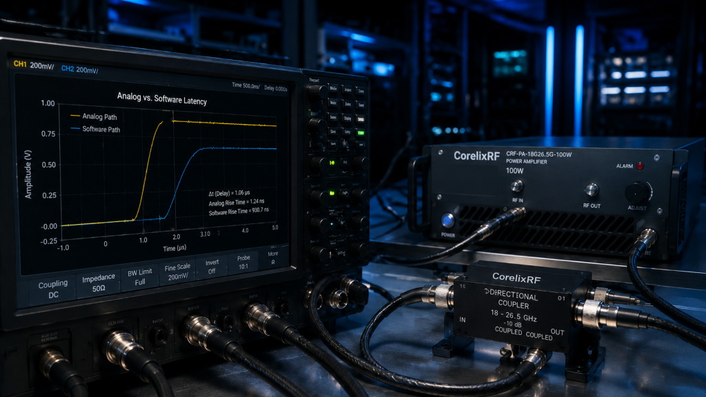
Field troubleshooting requires precise instrumentation for transient event capture. Standard spectrum analyzers lack sufficient time-domain resolution for these microsecond faults. Engineers must deploy fast oscilloscopes synchronized with high-directivity directional couplers. You insert this coupler directly between your amplifier output and antenna feed. Ready for the good part? We set oscilloscope triggers specifically for reverse power threshold breaches. When a simulated antenna break occurs, we measure exact response delays. Software polling systems show distinct lag times before shutting down bias currents. We capture these fatal milliseconds on screen for clear verification. This hard evidence proves why digital routines fail during sudden VSWR events. Our troubleshooting protocol isolates protection latency from general component failure. Managing an internal team of 400 employees reinforces the necessity of strict, repeatable diagnostic procedures.
Field Troubleshooting Tool Checklist
| Instrument | Function | Target Metric |
| Fast Oscilloscope | Time-domain analysis | Microsecond capture |
| Directional Coupler | Signal tapping | >20 dB directivity |
| Variable Attenuator | Load simulation | VSWR mismatch creation |
5. How do frequency-hopping algorithms mask impending hardware failures?
Blind spots during hop transitions
Software averaging errors
False negatives
Radar controllers utilize complex algorithms for spectrum evasion. These systems constantly adjust output frequencies across wide bandwidths. Software-based VSWR monitors often implement averaging functions for signal smoothing. This averaging creates dangerous blind spots during rapid frequency transitions. But here’s the kicker: transient reflections get mathematically filtered out as noise. Intermittent connection issues generate short reflection spikes during specific frequency hops. A digital monitor records a false negative due to temporal averaging. Operators see green status indicators while physical damage accumulates quietly. We observe this phenomenon frequently during system integration testing phases. Raw analog signals provide true reflections of actual hardware health. Relying solely on filtered digital logs leads engineers down wrong diagnostic paths. True engineering requires unfiltered access to physical layer realities.
6. What specific hardware limits define the 18 to 26.5 GHz operational band?
Waveguide flange tolerances
Connector mating cycles
Insertion loss scaling
Operating within K-band frequencies demands absolute mechanical precision. The 18,000 through 26,500 MHz spectrum requires tight waveguide flange tolerances. Small microscopic gaps in WR42 connections introduce unacceptable insertion loss scaling. Standard coaxial interfaces also suffer under these high-frequency constraints. The 2.92mm-F input connectors possess strictly limited mating cycles before degrading. Let me explain: every physical connection represents a potential failure point. Field technicians must utilize proper torque wrenches for every installation. Over-tightening damages delicate center pins permanently. Under-tightening causes unpredictable phase shifts and localized heating. Our engineering team designs systems respecting these unforgiving physical boundaries. You cannot force low-frequency practices into millimeter-wave environments without suffering consequences. Decades of manufacturing experience prove that mechanical interfaces dictate overall RF performance.
CorelixRF Frequency Band Specifications
| Parameter | Specification | Notes |
| Frequency Range | 18,000 – 26,500 MHz | Full band coverage |
| Input Connector | 2.92mm-F | High precision required |
| Output Connector | WR42 Waveguide | Requires proper torque |
7. Why is hardware-level reverse power monitoring mandatory for Ka-band/K-band systems?
Microsecond reaction times
Analog comparator logic
Bypassing microprocessor latency
High-frequency power amplification necessitates instantaneous fault protection mechanisms. Hardware-level reverse power monitoring provides microsecond reaction times consistently. We utilize dedicated analog comparator logic circuits for direct measurement. This architecture entirely bypasses any unpredictable microprocessor latency issues. Truth be told: an analog circuit acts the moment thresholds break. A directional coupler feeds reflected voltage directly into high-speed comparators. Once reverse power exceeds safe limits, bias voltages drop immediately. This hardwired reflex saves expensive GaN transistors from total annihilation. We refuse to entrust component survival to software execution loops. True reliability stems from deterministic physical reactions grounded in solid engineering. System integrators building electronic warfare platforms demand this exact level of uncompromising hardware assurance.
8. How does the CorelixRF CRF-PA-18000M26500M-100W address VSWR transients?
Built-in analog alarm protection
GaN resilience
Overdrive thresholds
Our factory designed this specific unit for harsh operational realities. The CRF-PA-18000M26500M-100W features pure built-in analog alarm protection circuitry. We combine advanced GaN technology with relentless hardware-based safeguarding loops. The system monitors temperature, current, and reverse power continuously. Here is the secret: our protection circuits operate independently from external control interfaces. A 100 W rated output demands serious defense against overdrive thresholds. When severe VSWR conditions occur, the unit cuts power within microseconds. It provides a reliable 50 dB gain across the entire band safely. Our engineering truth focuses on physical survivability above all else. This approach prevents the exact burnout scenarios common in inferior designs. This unit maintains stability up to 50 degrees Celsius operating temperature.
CRF-PA-18000M26500M-100W Electrical Capabilities
| Parameter | Typical Value | Conditions |
| Rated Output Power | 100 W | Continuous Wave |
| Gain Flatness | ±6 dB | Across full band |
| Input VSWR | 2:1 | Maximum threshold |
9. What are the key integration parameters for deploying this 100W amplifier?
19-inch 4U rack mechanics
AC 220V power supply scaling
WR42 waveguide mating
System integrators require clear mechanical and electrical boundaries for deployment. This module occupies a standard 19-inch 4U rack space. Weighing 29 kg, it demands proper support rails inside vehicle cabinets. Power delivery relies on robust AC 220V inputs with tight voltage regulations. Now consider this: high-power K-band energy requires specialized routing hardware. The WR42 output interface demands meticulous waveguide mating procedures. Integrators must account for 800 W total power consumption during thermal planning. We implement integrated air cooling fans managing internal heat dissipation. Proper ventilation clearances remain non-negotiable for sustained operational stability. We supply complete mechanical outline drawings supporting precise system-level modeling. The rear panel supports RS485 and LAN interfaces for remote monitoring.
Integration and Mechanical Limits
| Aspect | Detail | Implication |
| Package Size | 19”, 4U | Requires standard rack |
| Power Supply | AC 220V±10%, 50/60Hz | Dedicated line needed |
| Cooling Method | Air cooling | Ventilation mandatory |
10. How can system integrators verify VSWR protection efficacy in the field?
Simulated load mismatch testing
Thermal imaging during stress tests
Fault log extraction
Verification requires controlled stress testing under realistic field conditions. Engineers must perform simulated load mismatch testing using variable attenuators. We deliberately introduce high reflection states while monitoring amplifier responses. Thermal imaging cameras track GaN package temperatures during these extreme stress tests. Let’s look at the facts: a working protection circuit prevents any temperature spikes. The unit should latch off before heat generation begins. Afterward, technicians verify analog protection triggers through interface fault log extraction. We provide RS485 and LAN control interfaces specifically for this diagnostic feedback. This testing proves our hardware defense mechanisms operate exactly as specified. You cannot guess about reliability when deploying multi-million dollar radar assets. Field verification separates marketing claims from actual engineering performance.
Hardware-level analog protection definitively solves catastrophic transistor failures caused by software latency during antenna breakages. Upgrading to deterministic VSWR defense mechanisms safeguards expensive RF infrastructure. Contact CorelixRF engineering teams today for detailed integration documentation regarding the CRF-PA-18000M26500M-100W. Protect your radar systems with proven physical engineering rather than vulnerable digital code.
FAQ Section
Q1: What is software polling VSWR delay?
Software polling VSWR delay represents the time gap between a physical antenna breakage and a digital microprocessor recognizing the resulting signal reflection. This delay often lasts milliseconds, allowing massive reverse power to burn out sensitive amplifier components before protection engages.
Q2: How does analog VSWR protection work?
Analog protection uses hardware comparators directly tied to directional couplers. When reverse voltage exceeds safe thresholds, the analog circuit instantly cuts bias power to the transistors, bypassing slower digital processing entirely for microsecond reaction times.
Q3: What causes structural failures in high-frequency radar antennas?
Antenna failures stem from severe mechanical shocks, sustained high-frequency vibration fatigue, and corrosive environmental factors like salt fog. These elements degrade structural joints until a minor physical impact shatters the waveguide or feedhorn.
Q4: What are the risks of frequency-hopping blind spots?
During rapid frequency shifting, software monitors often average out reflection data to reduce noise. This averaging mathematically erases brief, severe VSWR spikes, creating blind spots where hardware damage accumulates unnoticed by system operators.
Q5: How can system integrators verify VSWR protection efficacy in the field?
Integrators use fast oscilloscopes and variable attenuators to simulate load mismatches. By triggering a fault and measuring the exact response time before power shuts down, they prove whether the protection circuit acts fast enough to save the module.
Turn VSWR behavior into factory acceptance evidence
High VSWR protection should be defined with mismatch scenario, foldback or shutdown threshold, recovery logic, alarm output, thermal limit and FAT evidence. This makes protection claims measurable for procurement.
Recommended next step: send the operating band, output power target, duty cycle, load condition, control interface, protection or thermal limits and required FAT documents. CorelixRF can review this How to Implement Radar VSWR Protection During Antenna Breakage? requirement against standard RF amplifier platforms, RF front-end options and controlled customization paths.