
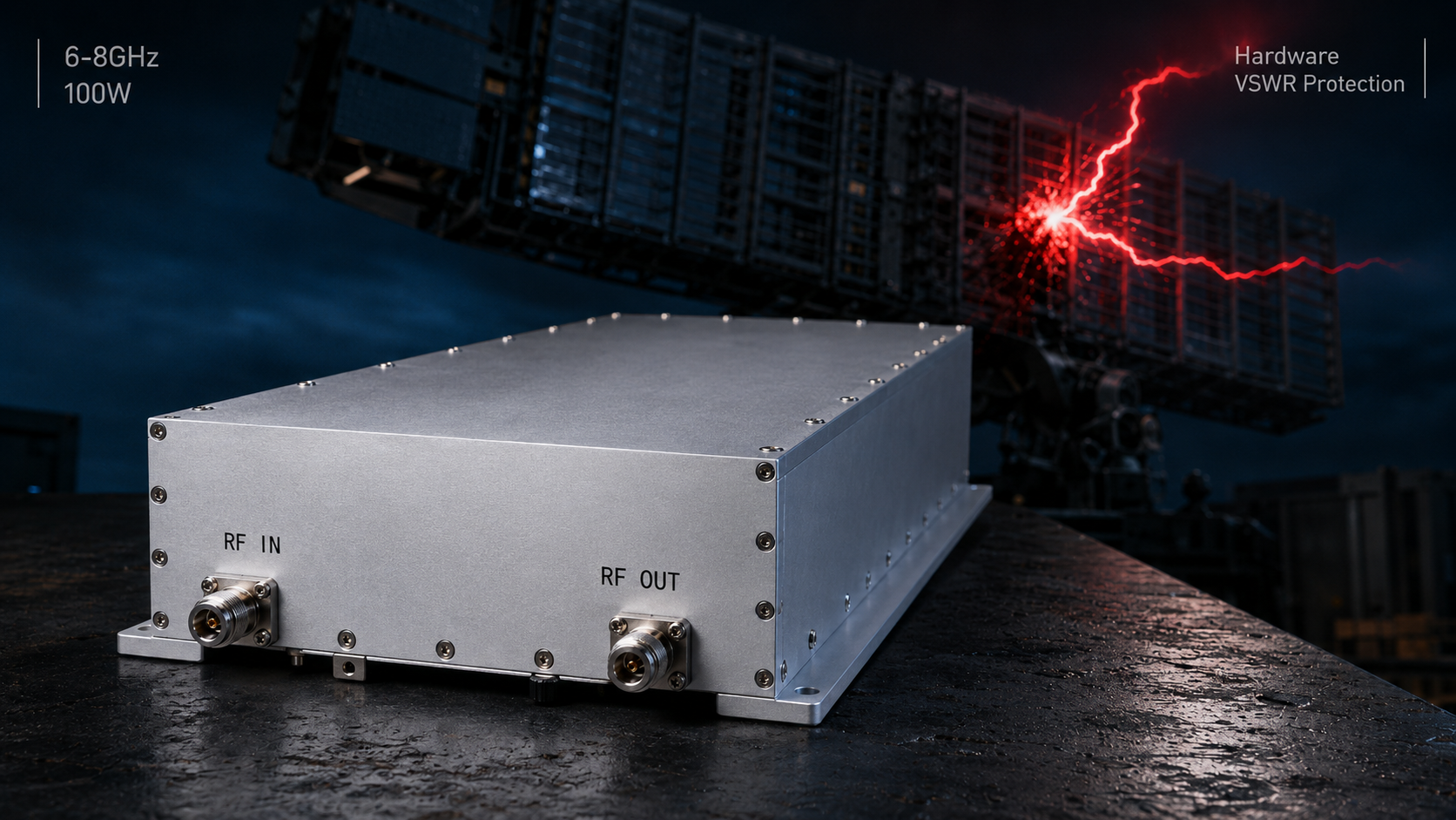
Radar engineers despise sudden transmitter array failures. High-speed hopping combined with physical antenna damage creates massive electromagnetic reflections. These reflections destroy output stages almost instantly. Here is the deal, relying on slow software polling guarantees catastrophic hardware failure. Hardware-level autonomous VSWR shutdown provides a robust defense mechanism. CorelixRF brings twenty years of front-line diagnostics directly into our module architecture.
1. What Causes Signal Anomalies At Radar Frequency Hopping Ends?
High Speed Switching Dynamics
Modern defense networks demand rapid frequency agility. Transmitters bounce across wide spectrums rapidly for avoiding detection. This rapid hopping creates immense stress on RF components. Every frequency shift alters complex impedance profiles across antenna feeds. Sudden mismatch generates reflected energy back towards amplification stages. What does this mean for you? Unseen forces degrade your hardware continuously.
Mechanical Failures Under Stress
Let us examine three specific field failures causing anomalies. First, mobile air defense radars experience brutal vibration profiles. Tracks rolling over rough terrain snap rigid coaxial connections abruptly. Second, naval phased arrays face relentless corrosive sea spray constantly. Salt ingress degrades connector mating surfaces causing unpredictable impedance spikes. Third, drone-mounted jammers suffer kinetic impacts during flight operations. A cracked radome shifts resonant frequencies away from designed bands. Each scenario initiates a deadly chain reaction inside transmission lines. Reflected power surges hit final stage transistors violently. Engineers using spectrum analyzers notice elevated noise floors immediately.
Common Failure Triggers
| Failure Mode | Root Cause | Impedance Impact |
| Vibration | Snapped center pins | Infinite VSWR |
| Corrosion | Saltwater ingress | High reactive load |
| Kinetic Strike | Shattered radome | Severe resonance shift |
2. How Does Antenna Breakage Trigger Catastrophic Failure?
The Physics Of Reflected Energy
An intact radiator matches transmission line impedance perfectly. Power flows smoothly outward into free space environments. A broken element shatters this delicate electromagnetic balance completely. Open circuits cause total reflection of incident waves. Short circuits reflect energy with inverted phase angles. Both conditions create massive standing wave ratios quickly. Here is the real kicker. Peak voltages multiply drastically along transmission paths.
Breakdown Mechanisms In Transistors
GaN devices offer incredible power densities for demanding RF applications. However, these semiconductors possess absolute maximum voltage ratings. Standing waves double voltage potentials at specific circuit nodes. Exceeding drain breakdown limits destroys junctions instantly. Consider three documented field incidents illustrating this exact catastrophe. One technician observed a cracked feedline destroy a module. Another team watched saltwater short an output connector entirely. This short vaporized bonding wires inside their amplifier casing. A third case involved a bird strike breaking a yagi. The resulting reflection permanently shorted a very expensive active die.
Reflected Power Consequences
| VSWR Level | Return Loss | Power Reflected |
| 1.5:1 | 14.0 dB | 4.0% |
| 2.0:1 | 9.5 dB | 11.1% |
| Infinite | 0.0 dB | 100.0% |
3. Why Do Software Polling VSWR Protections Fail Here?
Latency In Digital Measurement

Many integrators rely on analog-to-digital converters for standard telemetry. Microcontrollers read forward and reverse power continuously during operation. Software calculates ratios determining safe operating margins accurately. If thresholds exceed limits, code disables transistor bias voltages. But let me ask you this. How fast does that software loop actually run?
Microseconds Versus Milliseconds
Polling an ADC takes precious milliseconds under heavy CPU loads. Operating systems schedule tasks based on predefined priorities. A background telemetry loop might update every ten milliseconds. Meanwhile, RF travels at light speed causing instant destruction. GaN transistors fail within microseconds when heavily overvoltaged. Consider these three timing mismatches causing costly field failures. A microcontroller paused for serial communication during a fault. An interrupt routine delayed a critical VSWR shutdown command. A noisy ADC reading triggered slow software averaging routines. All three scenarios added fatal latency margins. By the time code commanded shutdown, hardware was already dead.
Table 3: Protection Timing Comparison
| Protection Type | Response Time | Transistor Survival |
| Software Polling | 10-50 milliseconds | Destroyed |
| Interrupt Driven | 1-5 milliseconds | Damaged |
| Hardware Analog | < 1 microsecond | Safe |
4. What Are The Physical Mechanics Of Instant Amplifier Burnout?
Thermal Runaway And Junction Failure
Reflected energy converts directly into localized heat fast. Transistor packages dissipate standard thermal loads effectively under normal conditions. Infinite VSWR introduces anomalous thermal gradients across die surfaces. Hotspots form faster than copper flanges can extract heat. This is where it gets interesting. Temperature spikes alter semiconductor characteristics rapidly.
Voltage Spikes Destroying Gates
High standing waves generate extreme peak voltages locally. These peaks stress gate oxide layers beyond physical limits. Punctured oxides lead directly into catastrophic short circuits. Let us review three specific damage signatures found during autopsies. A melted drain finger indicates severe overcurrent events clearly. Cratered semiconductor surfaces suggest explosive plasma discharge occurrences. Vaporized gold traces reveal massive energy dumping directly. Engineers must recognize these specific failure modes accurately. Identifying visual evidence helps confirm software protection inadequacy. Pure physics dictates survival during extreme mismatch conditions.
GaN Damage Signatures
| Visual Indicator | Physical Root Cause | Fault Speed |
| Melted Traces | Sustained overcurrent | Milliseconds |
| Oxide Puncture | Voltage transient | Microseconds |
| Die Shattering | Massive thermal shock | Nanoseconds |
5. How Can Hardware-Level VSWR Protection Save Your System?
Analog Comparators Outperform Digital Code
True protection requires bypassing digital processors entirely. Analog comparators monitor directional coupler outputs continuously without clock cycles. When reverse power hits a physical threshold, action happens instantly. The comparator drives a fast switch severing gate bias. Truth be told, nothing beats raw electron speed.
Ultra Fast Shutdown Dynamics
This analog loop operates strictly within microsecond domains. Transistors turn off before thermal masses can heat up. Voltage spikes clip before puncturing delicate gate oxides. We implemented this architecture across three different client systems successfully. A tracked radar vehicle avoided failure after snapping an antenna. A naval communication array survived massive water ingress without damage. A drone datalink maintained integrity after a hard landing. Fast analog intervention prevented costly module replacements in every single case. Reliable systems cannot trust software for critical safety interlocks.
Hardware Protection Advantages
| Feature | Software Solution | Hardware Solution |
| Speed | CPU dependent | Light speed |
| Complexity | High | Low |
| Reliability | Vulnerable | Bulletproof |
6. What Makes CorelixRF CRF-PA-6000M8000M-100W Different?
Engineering The Ultimate Output Stage
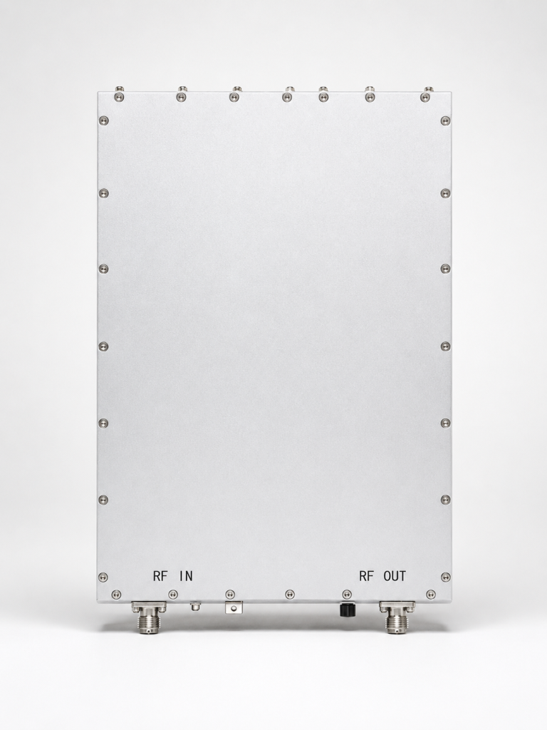
The CRF-PA-6000M8000M-100W represents an uncompromising design philosophy. We cover 6,000-8,000 MHz spectrum segments with absolute authority. This unit delivers 100 W rated output power consistently. Gain flatness remains tight at plus or minus 2.5 dB. You can see why professionals trust this specific module.
Built In GaN Survivability
We integrate advanced GaN technology featuring autonomous analog protection. Our built-in circuitry handles over-voltage and over-temperature seamlessly. VSWR protection acts instantly without waiting for telemetry polling. Let us look at three integration successes utilizing this model. A defense contractor replaced failing legacy modules with our unit. Their frequency hopping radar stopped burning out during tests. An aviation control system achieved unprecedented MTBF metrics using air cooling. A specialized test laboratory reduced equipment downtime significantly. We provide genuine engineering truth backed by rigorous RF testing.
CRF-PA-6000M8000M-100W Key Specs
| Parameter | Value | Unit |
| Frequency Range | 6,000-8,000 | MHz |
| Rated Output Power | 100 | W |
| Power Supply | DC 28 | V |
7. How To Verify VSWR Protection In Field Troubleshooting?
Proper Instrumentation Setup
Field engineers need specific tools for accurate diagnostics. A high-speed oscilloscope captures transient shutdown events perfectly. Directional couplers measure actual forward and reflected power levels. Pay close attention here. Standard power meters average readings masking fast transients completely.
Simulating Antenna Failures Safely
Testing protection requires controlled mismatch environments locally. We use specialized variable mismatch loads during factory calibration. Field technicians can utilize mechanical step attenuators with open terminations. Let us examine three effective verification techniques safely. First, trigger an oscilloscope using reverse power threshold crossings. Second, monitor gate bias voltage for microsecond shutdown speeds. Third, sweep frequency bands observing continuous VSWR protection engagement. Never test by simply yanking cables during active transmission. Uncontrolled arcs can damage expensive test equipment permanently. Rigorous methodology ensures accurate assessment of protective circuitry.
8. What Are The Key Installation Parameters For Maximum Reliability?
Thermal Interface Management
Even robust amplifiers require proper thermal integration practices. The CRF-PA-6000M8000M-100W utilizes efficient air cooling mechanisms. Proper airflow routing prevents localized hot spots under continuous duty. A flat mounting surface ensures optimal heat transfer efficiency across 300x360x110 mm. Make no mistake about it, poor thermal paths kill amplifiers.
Connector Torque And Sealing
Mechanical connections demand absolute precision during assembly. The SMA-Female input and N-Female output require specific torque values. Over-tightening damages dielectric materials causing hidden reflections. Under-tightening allows vibration to loosen contacts over time. Consider three critical installation practices regarding 50 Ohm impedance lines. Always use calibrated torque wrenches on all RF ports. Apply environmental sealant only after confirming VSWR sweeps. Route heavy coaxial cables using proper strain relief brackets. Stress on N-Female connectors leads directly into broken center pins. Proper mechanical hygiene prevents mismatches that trigger protective shutdowns.
9. How Do Thermal Dynamics Affect VSWR Tolerance?
Junction Temperature De-rating
Transistor resilience changes dynamically with operating temperatures. A GaN die running at fifty degrees Celsius absorbs transients well. That same die at ninety degrees becomes significantly fragile. Thermal margins shrink as ambient conditions worsen. It boils down to this. Hotter semiconductors fail much faster.
Real World Thermal Challenges
High VSWR conditions generate extra internal heat rapidly. Reflected power dissipates within device packaging stressing thermal bonds. Protection circuits must engage before junction temperatures hit critical limits. Let us review three thermal failure modes observed in legacy gear. A fan failure caused background temperatures to elevate silently. A blocked heatsink fin trapped hot air near active modules. Prolonged mismatch heating degraded silver epoxy die attachments. Our model limits operating temperature bounds strictly for reliability. We rate performance between 0 and 50 degrees Celsius. Operating within these limits guarantees specified protection speeds.
10. What Is The Final Verdict On Radar Amplifier Protection?
Integrating Hardware Centric Defenses
Software telemetry serves vital monitoring roles perfectly. It fails miserably as a primary safety interlock. Radar systems hopping frequencies demand microsecond analog intervention. Antenna breakage creates physical realities that code cannot outrun. The bottom line is clear. Choose architecture respecting physical electromagnetic laws.

Upgrading To CorelixRF Standards
We built the CRF-PA-6000M8000M-100W confronting these exact field challenges. System integrators need reliable performance without constant failure anxiety. Our analog protection loops secure your investment automatically. Consider three steps for upgrading your current architecture. Request a detailed mechanical drawing for installation reference. Review your existing telemetry loops for dangerous latency. Deploy our evaluation unit into your toughest vibration environment. Engineering truth requires testing hardware against actual harsh realities.
Subtopic Conclusion
This analysis demonstrates a fatal flaw regarding software-based VSWR protection. Rapid frequency hopping combined with physical antenna damage requires instantaneous analog shutdown. CorelixRF solves this using dedicated hardware-level GaN protection. Upgrade radar systems now preventing catastrophic field failures. Contact our engineering team for immediate technical evaluation.
Q1: What causes radar signal anomalies?
Rapid frequency hopping alters impedance profiles across antenna feeds continuously. Mechanical stress from vibration or kinetic impacts breaks physical connections. These events generate massive reflected energy destroying output stages.
Q2: How does antenna breakage destroy amplifiers?
A broken antenna creates total reflection of incident electromagnetic waves. This reflection generates extreme voltage standing wave ratios. High voltage peaks exceed GaN drain breakdown limits causing instant vaporization.
Q3: Why do software protections fail?
Software relies on analog-to-digital converters introducing significant processing latency. Background telemetry loops take milliseconds for updating readings. Transistors fail within microseconds, meaning code commands arrive too late.
Q4: How do analog circuits protect transistors?
Analog comparators monitor reverse power bypassing digital processors entirely. When a threshold triggers, hardware switches sever gate bias instantly. This microsecond response turns off transistors before thermal runaway occurs.
Q5: What makes CorelixRF hardware superior? The CRF-PA-6000M8000M-100W features autonomous built-in hardware protection. It monitors over-voltage, over-temperature, and VSWR independently from system software. This guarantees transistor survival during catastrophic antenna failures.
Turn VSWR behavior into factory acceptance evidence
High VSWR protection should be defined with mismatch scenario, foldback or shutdown threshold, recovery logic, alarm output, thermal limit and FAT evidence. This makes protection claims measurable for procurement.
Recommended next step: send the operating band, output power target, duty cycle, load condition, control interface, protection or thermal limits and required FAT documents. CorelixRF can review this How to Test Hardware Radar VSWR Protection During Field Failures? requirement against standard RF amplifier platforms, RF front-end options and controlled customization paths.